


Drive control and features
75
Master/Follower distance correction
The purpose of the master/follower distance correction is to measure the distance
between the two probe positions and compare it with the distance between
reference positions
and
. If there is
a deviation, a correction is carried out on both the drive synchron reference
and actual position
.
Note:
In master/follower distance correction, the follower must always be in
synchron control mode. If the follower is not used in synchron control mode,
adjusting the drive synchron reference (
) will not affect the
operation of the drive, and the correction cannot be carried out properly.
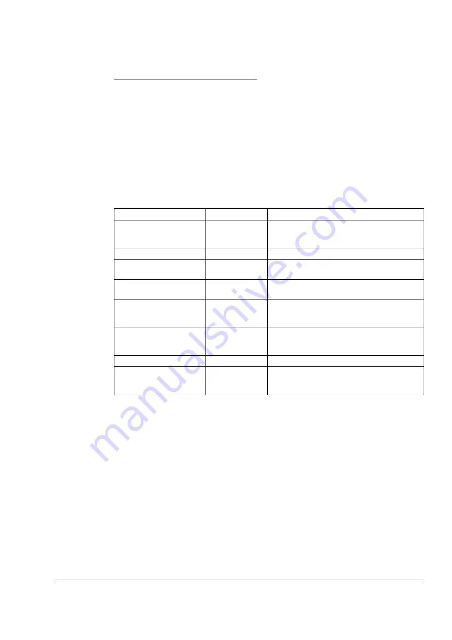
Example 1:
Roll-over axis application. Master and follower proximity switches are
located at 0°.
Parameter
Setting
Information
Positioning is between 0 and 1 revolutions, ie,
after 360°, the position calculation starts from 0°
again.
All position values are in degrees
Same as for
Synchron gear ratio is 1.
Cyclic master/follower distance correction
Rising edge of encoder 1 digital input DI1.
Source of the actual position latching command
(proximity switch signal source)
Rising edge of encoder 1 digital input DI2.
Source of the master position latching command
(proximity switch signal source)
0°
Reference position for the actual position probe
-120°
Reference position for the master position probe,
ie, follower is 120° [(0°-120°)-(0°-0°)] behind the
master.
Summary of Contents for ACSM1 Series
Page 1: ...ABB motion control drives Firmware manual ACSM1 motion control program ...
Page 4: ......
Page 34: ...Drive programming using PC tools 34 ...
Page 86: ...Drive control and features 86 ...
Page 265: ...Parameters and firmware blocks 265 1 100 us 100 µs 2 1 ms 1 ms 3 50 ms 50 ms ...
Page 302: ...Parameter data 302 ...
Page 422: ...Application program template 422 ...
Page 430: ...Appendix A Fieldbus control 430 ...
Page 500: ...Appendix D Application examples 500 ...
Page 508: ...Appendix E Control chain and drive logic diagrams 508 ...
Page 510: ...3AFE68848270 REV H EN 2015 06 26 Contact us www abb com drives www abb com drivespartners ...


