Drive control and features
42
Autophasing
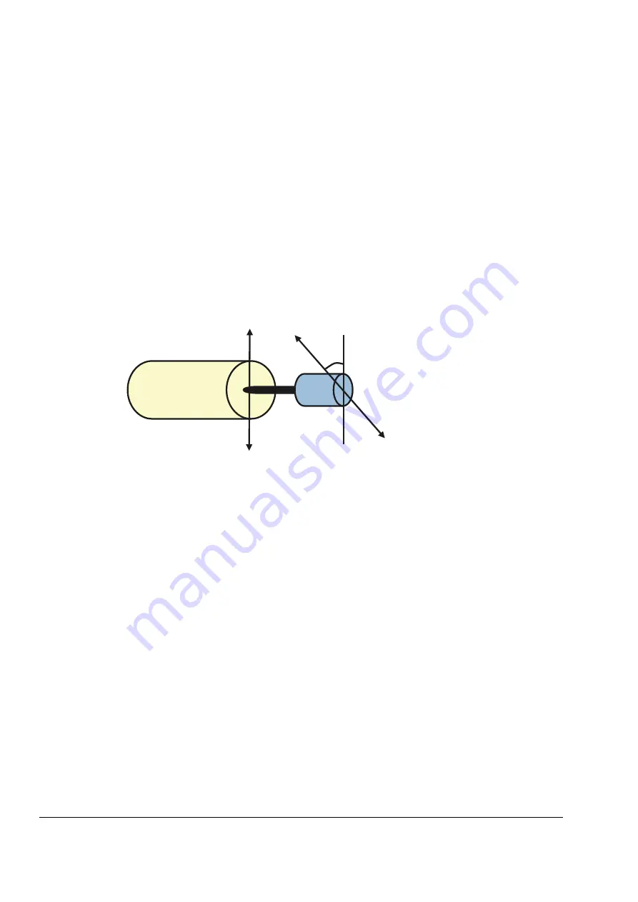
Autophasing is an automatic measurement routine to determine the angular position
of the magnetic flux of a permanent magnet synchronous motor or the magnetic axis
of a synchronous reluctance motor. The motor control requires the absolute position
of the rotor flux to control the motor torque accurately.
Sensors like absolute encoders and resolvers indicate the rotor position at all times
after the offset between the zero angle of rotor and that of the sensor has been
established. On the other hand, a standard pulse encoder determines the rotor
position when it rotates but the initial position is not known. However, a pulse
encoder can be used as an absolute encoder if it is equipped with Hall sensors,
albeit with coarse initial position accuracy. The Hall sensors generate so-called
commutation pulses that change their state six times during one revolution, so it is
only known within which 60° sector of a complete revolution the initial position is.
The autophasing routine is performed with permanent magnet synchronous motors
in the following cases:
1. One-time measurement of the rotor and encoder position difference when an
absolute encoder, a resolver, or an encoder with commutation signals is used
2. At every power-up when an incremental encoder is used
3. With the open-loop motor control, repetitive measurement of the rotor position at
every start.
In the open-loop mode, the zero angle of the rotor is determined before the start. In
the closed loop mode, the actual angle of the rotor is determined with autophasing
when the sensor indicates the zero angle. The offset of the angle must be
determined because the actual zero angles of the sensor and the rotor do no usually
match. The autophasing mode determines how this operation is done both in the
open loop and closed loop modes.
Note:
In the open loop mode, the motor always turns when it is started as the shaft is
turned towards the remanence flux.
A rotor position offset used in motor control can also be given by the user. See
parameter
.
ș
Absolute encoder/resolver
Rotor
N
S
Summary of Contents for ACSM1 Series
Page 1: ...ABB motion control drives Firmware manual ACSM1 motion control program ...
Page 4: ......
Page 34: ...Drive programming using PC tools 34 ...
Page 86: ...Drive control and features 86 ...
Page 265: ...Parameters and firmware blocks 265 1 100 us 100 µs 2 1 ms 1 ms 3 50 ms 50 ms ...
Page 302: ...Parameter data 302 ...
Page 422: ...Application program template 422 ...
Page 430: ...Appendix A Fieldbus control 430 ...
Page 500: ...Appendix D Application examples 500 ...
Page 508: ...Appendix E Control chain and drive logic diagrams 508 ...
Page 510: ...3AFE68848270 REV H EN 2015 06 26 Contact us www abb com drives www abb com drivespartners ...


