


Drive control and features
46
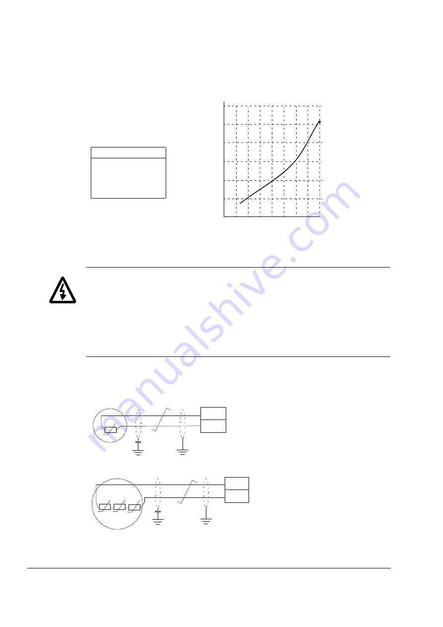
The figure below shows typical KTY84 sensor resistance values as a function of the
motor operating temperature.
It is possible to adjust the motor temperature supervision limits and select how the
drive reacts when overtemperature is detected.
WARNING!
As the thermistor input on the JCU Control Unit is not insulated
according to IEC 60664, the connection of the motor temperature sensor requires
double or reinforced insulation between motor live parts and the sensor. If the
assembly does not fulfil the requirement,
- the I/O board terminals must be protected against contact and must not be
connected to other equipment
or
- the temperature sensor must be isolated from the I/O terminals.
The figure below shows a motor temperature measurement when thermistor input
TH is used.
1000
2000
3000
ohm
T (
°
C)
KTY84 scaling
90 °C = 936 ohm
110 °C = 1063 ohm
130 °C = 1197 ohm
150 °C = 1340 ohm
-100
0
0
100
200
300
Motor
T
JCU Control Unit
TH
AGND
10 nF
One PTC or KTY84 sensor
Motor
T
JCU Control Unit
TH
AGND
T
T
Three PTC sensors
10 nF
Summary of Contents for ACSM1 Series
Page 1: ...ABB motion control drives Firmware manual ACSM1 motion control program ...
Page 4: ......
Page 34: ...Drive programming using PC tools 34 ...
Page 86: ...Drive control and features 86 ...
Page 265: ...Parameters and firmware blocks 265 1 100 us 100 µs 2 1 ms 1 ms 3 50 ms 50 ms ...
Page 302: ...Parameter data 302 ...
Page 422: ...Application program template 422 ...
Page 430: ...Appendix A Fieldbus control 430 ...
Page 500: ...Appendix D Application examples 500 ...
Page 508: ...Appendix E Control chain and drive logic diagrams 508 ...
Page 510: ...3AFE68848270 REV H EN 2015 06 26 Contact us www abb com drives www abb com drivespartners ...


