


Drive control and features
57
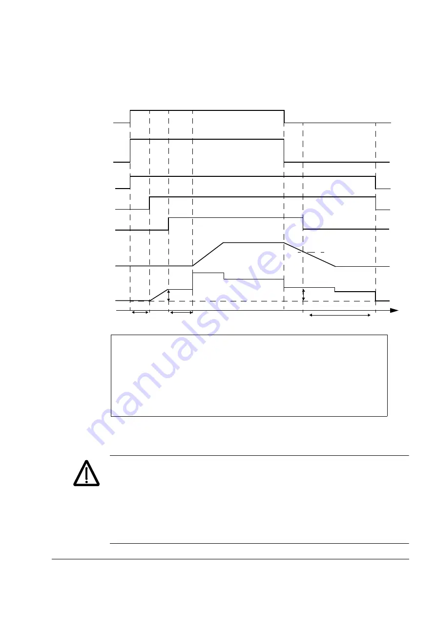
Operation time scheme
The simplified time scheme below illustrates the operation of the brake control
function.
Example
The figure below shows a brake control application example.
WARNING!
Make sure that the machinery into which the drive with brake control
function is integrated fulfils the personnel safety regulations. Note that the frequency
converter (a Complete Drive Module or a Basic Drive Module, as defined in IEC
61800-2), is not considered as a safety device mentioned in the European
Machinery Directive and related harmonised standards. Thus, the personnel safety
of the complete machinery must not be based on a specific frequency converter
feature (such as the brake control function), but it has to be implemented as defined
in the application specific regulations.
T
s
Start torque at brake release (parameter
)
T
mem
Stored torque value at brake close (signal
)
t
md
Motor magnetising delay
t
od
)
n
cs
Brake close speed (parameter
)
t
cd
Brake close delay (parameter
)
Start cmd
Modulating
Ref_Running
Brake open cmd
Ramp output
Torque ref
time
t
od
t
cd
n
cs
T
s
Ramp input
t
md
1
2
3
4
5
6
7
T
mem
Summary of Contents for ACSM1 Series
Page 1: ...ABB motion control drives Firmware manual ACSM1 motion control program ...
Page 4: ......
Page 34: ...Drive programming using PC tools 34 ...
Page 86: ...Drive control and features 86 ...
Page 265: ...Parameters and firmware blocks 265 1 100 us 100 µs 2 1 ms 1 ms 3 50 ms 50 ms ...
Page 302: ...Parameter data 302 ...
Page 422: ...Application program template 422 ...
Page 430: ...Appendix A Fieldbus control 430 ...
Page 500: ...Appendix D Application examples 500 ...
Page 508: ...Appendix E Control chain and drive logic diagrams 508 ...
Page 510: ...3AFE68848270 REV H EN 2015 06 26 Contact us www abb com drives www abb com drivespartners ...


