Chapter 5: C4c CMTS Installation Requirements
STANDARD Revision 1.0
C4® CMTS Release 8.3 User Guide
© 2016 ARRIS Enterprises LLC. All Rights Reserved.
161
In the event of a power fault on a branch:
The electronic breaker for that branch detects the failure and removes power from that branch.
A system power alarm is generated.
The green power OK LED for that branch is turned off and the corresponding branch’s red power fault LED is turned on.
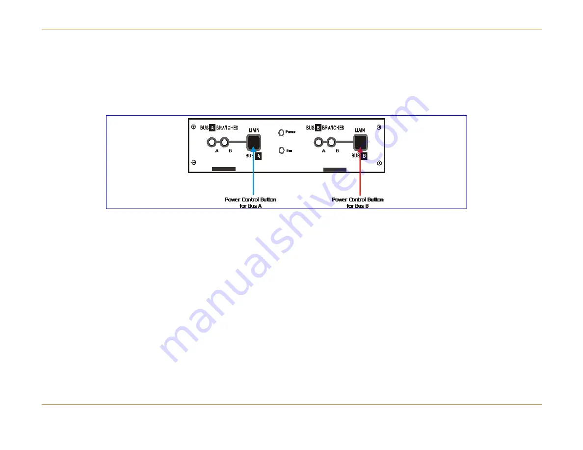
Figure 41:
Power Control Buttons
Automatic Card Recovery for DC Voltage
Each front module of the C4c CMTS contains multiple DC-to-DC converters to supply various required voltages to devices
on the modules. There are also multiple voltage measurement devices that continuously measure the voltage levels while
the maintenance software generates log messages for voltage levels that are outside the specified range for each
measurement point.
In many cases, a voltage measurement that is only slightly out of specification will not affect the performance of a module
and should be considered only as a warning to the operator to take action in the near future. In this case, a failover to a
standby module might cause more issues than remaining on the current active module even though it has a voltage plane
that is slightly out of specification. On the other hand, voltage planes that are far out of specification can cause the module
to stop functioning properly. In this case, sometimes the improper function is detected by maintenance and the card is
taken out of service. There are some cases in which a voltage plane can fail causing the module to stop functioning
properly without an automatic recovery.


