


Chapter 26 Deserial Serial Peripheral Interface (DSPI)
MPC5606BK Microcontroller Reference Manual, Rev. 2
634
Freescale Semiconductor
Section 26.5.4, DSPI Clock and Transfer Attributes Registers 0–5 (DSPIx_CTARn)
.
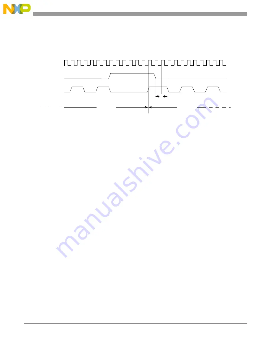
, time A shows the one clock interval. Time B is user programmable from a minimum of
two system clocks.
Figure 26-22. Polarity switching between frames
26.6.6
Continuous serial communications clock
The DSPI provides the option of generating a continuous SCK signal for slave peripherals that require a
continuous clock.
Continuous SCK is enabled by setting the CONT_SCKE bit in the DSPI
x
_MCR. Continuous SCK is valid
in all configurations.
Continuous SCK is only supported for CPHA = 1. Setting CPHA = 0 is ignored if the CONT_SCKE bit is
set. Continuous SCK is supported for modified transfer format.
Clock and transfer attributes for the continuous SCK mode are set according to the following rules:
•
The TX FIFO must be cleared before initiating any SPI configuration transfer.
•
When the DSPI is in SPI configuration, CTAR0 is used initially. At the start of each SPI frame
transfer, the CTAR specified by the CTAS for the frame should be CTAR0.
•
In all configurations, the currently selected CTAR remains in use until the start of a frame with a
different CTAR specified, or the continuous SCK mode is terminated.
The device is designed to use the same baud rate for all transfers made while using the continuous SCK.
Switching clock polarity between frames while using continuous SCK can cause errors in the transfer.
Continuous SCK operation is not guaranteed if the DSPI is put into module disable mode.
Enabling continuous SCK disables the CS to SCK delay and the After SCK delay. The delay after transfer
is fixed at one SCK cycle.
shows timing diagram for continuous SCK format with continuous
selection disabled.
NOTE
When in Continuous SCK mode, always use CTAR0 for the SPI transfer,
and clear the TXFIFO using the MCR[CLR_TXF] field before initiating
transfer.
CS
System clock
SCK
Frame 1
Frame 0
CPOL = 0
CPOL = 1
A
B
Summary of Contents for MPC5605BK
Page 2: ...This page is intentionally left blank...
Page 20: ...MPC5606BK Microcontroller Reference Manual Rev 2 20 Freescale Semiconductor...
Page 103: ...MPC5606BK Microcontroller Reference Manual Rev 2 Freescale Semiconductor 103 Clocks and power...
Page 645: ...MPC5606BK Microcontroller Reference Manual Rev 2 Freescale Semiconductor 643 Timers...
Page 715: ...MPC5606BK Microcontroller Reference Manual Rev 2 Freescale Semiconductor 713 ADC system...
Page 787: ...MPC5606BK Microcontroller Reference Manual Rev 2 Freescale Semiconductor 787 Memory...
Page 893: ...MPC5606BK Microcontroller Reference Manual Rev 2 Freescale Semiconductor 893 Integrity...
Page 943: ...MPC5606BK Microcontroller Reference Manual Rev 2 Freescale Semiconductor 943 Debug...


