


Chapter 25 FlexCAN
MPC5606BK Microcontroller Reference Manual, Rev. 2
588
Freescale Semiconductor
25.5.9.5
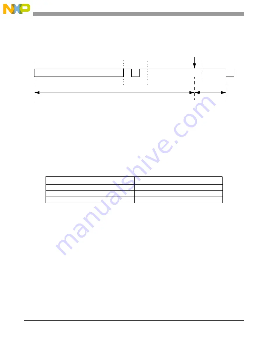
Arbitration and matching timing
During normal transmission or reception of frames, the arbitration, matching, move-in, and move-out
processes are executed during certain time windows inside the CAN frame, as shown in
.
Figure 25-18. Arbitration, match, and move time windows
When doing matching and arbitration, FlexCAN needs to scan the whole Message Buffer memory during
the available time slot. In order to have sufficient time to do that, the following requirements must be
observed:
•
A valid CAN bit timing must be programmed, as indicated in
•
The peripheral clock frequency cannot be smaller than the oscillator clock frequency, i.e., the PLL
cannot be programmed to divide down the oscillator clock
•
There must be a minimum ratio between the peripheral clock frequency and the CAN bit rate, as
specified in
A direct consequence of the first requirement is that the minimum number of time quanta per CAN bit must
be 8, so the oscillator clock frequency should be at least 8 times the CAN bit rate. The minimum frequency
ratio specified in
can be achieved by choosing a high enough peripheral clock frequency when
compared to the oscillator clock frequency, or by adjusting one or more of the bit timing parameters
(PRESDIV, PROPSEG, PSEG1, PSEG2). As an example, taking the case of 64 MBs, if the oscillator and
peripheral clock frequencies are equal and the CAN bit timing is programmed to have 8 time quanta per
bit, then the prescaler factor (P 1) should be at least 2. For prescaler factor equal to one and
CAN bit timing with 8 time quanta per bit, the ratio between peripheral and oscillator clock frequencies
should be at least 2.
25.5.10 Modes of operation details
25.5.10.1 Freeze mode
This mode is entered by asserting the HALT bit in MCR or when the MCU is put into Debug mode. In both
cases it is also necessary that the FRZ bit is asserted in MCR and the module is not in a low-power mode
Table 25-23. Minimum ratio between peripheral clock frequency and CAN bit rate
Number of Message Buffers
Minimum ratio
16
8
32
8
64
16
CRC (15)
EOF (7)
Interm
Start Move
Matching/Arbitration Window (24 bits)
Move
(bit 6)
Window
Summary of Contents for MPC5605BK
Page 2: ...This page is intentionally left blank...
Page 20: ...MPC5606BK Microcontroller Reference Manual Rev 2 20 Freescale Semiconductor...
Page 103: ...MPC5606BK Microcontroller Reference Manual Rev 2 Freescale Semiconductor 103 Clocks and power...
Page 645: ...MPC5606BK Microcontroller Reference Manual Rev 2 Freescale Semiconductor 643 Timers...
Page 715: ...MPC5606BK Microcontroller Reference Manual Rev 2 Freescale Semiconductor 713 ADC system...
Page 787: ...MPC5606BK Microcontroller Reference Manual Rev 2 Freescale Semiconductor 787 Memory...
Page 893: ...MPC5606BK Microcontroller Reference Manual Rev 2 Freescale Semiconductor 893 Integrity...
Page 943: ...MPC5606BK Microcontroller Reference Manual Rev 2 Freescale Semiconductor 943 Debug...


