


•
Two EX4200-24F switches
•
Four XFP uplink modules
Before you configure the LAGs, be sure you have:
•
Configured the Virtual Chassis switches. See “Example: Configuring a Virtual Chassis
with a Master and Backup in a Single Wiring Closet” on page 947.
•
Configured the uplink ports on the switches as trunk ports. See “Configuring Gigabit
Ethernet Interfaces (CLI Procedure)” on page 1153.
Overview and Topology
For maximum speed and resiliency, you can combine uplinks between an access switch
and a distribution switch into LAGs. Using LAGs can be particularly effective when
connecting a multimember Virtual Chassis access switch to a multimember Virtual
Chassis distribution switch.
The Virtual Chassis access switch in this example is composed of two member switches.
Each member switch has an uplink module with two 10-Gigabit Ethernet ports. These
ports are configured as trunk ports, connecting the access switch with the distribution
switch.
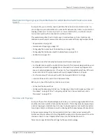
Configuring the uplinks as LAGs has the following advantages:
•
Link Aggregation Control Protocol (LACP) can optionally be configured for link
negotiation.
•
It doubles the speed of each uplink from 10 Gbps to 20 Gbps.
•
If one physical port is lost for any reason (a cable is unplugged or a switch port fails,
or one member switch is unavailable), the logical port transparently continues to
function over the remaining physical port.
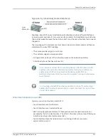
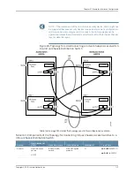
The topology used in this example consists of one Virtual Chassis access switch and one
Virtual Chassis distribution switch. The access switch is composed of two EX4200-48P
switches (SWA-0 and SWA-1), interconnected to each other with their Virtual Chassis
ports (VCPs) as member switches of Host-A. The distribution switch is composed of two
EX4200-24F switches (SWD-0 and SWD-1), interconnected with their VCPs as member
switches of Host-D.
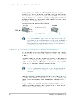
Each member of the access switch has an uplink module installed. Each uplink module
has two ports. The uplinks are configured to act as trunk ports, connecting the access
switch with the distribution switch. One uplink port from SWA-0 and one uplink port from
SWA-1 are combined as LAG
ae0
to SWD-0. This link is used for one VLAN. The remaining
uplink ports from SWA-0 and from SWA-1 are combined as a second LAG connection
(
ae1
) to SWD-1. LAG
ae1
is used for another VLAN.
Copyright © 2010, Juniper Networks, Inc.
1116
Complete Software Guide for Junos
®
OS for EX Series Ethernet Switches, Release 10.3
Summary of Contents for JUNOS OS 10.3 - SOFTWARE
Page 325: ...CHAPTER 17 Operational Mode Commands for System Setup 229 Copyright 2010 Juniper Networks Inc ...
Page 1323: ...CHAPTER 56 Operational Mode Commands for Interfaces 1227 Copyright 2010 Juniper Networks Inc ...
Page 2841: ...CHAPTER 86 Operational Commands for 802 1X 2745 Copyright 2010 Juniper Networks Inc ...
Page 3367: ...CHAPTER 113 Operational Mode Commands for CoS 3271 Copyright 2010 Juniper Networks Inc ...
Page 3435: ...CHAPTER 120 Operational Mode Commands for PoE 3339 Copyright 2010 Juniper Networks Inc ...
Page 3529: ...CHAPTER 126 Operational Mode Commands for MPLS 3433 Copyright 2010 Juniper Networks Inc ...


