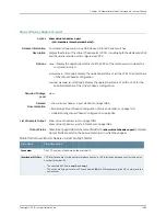

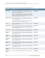


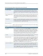

Table 161: Special Interface Types and Purposes
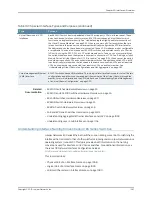
(continued)
Purpose
Type
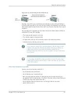
Each EX4200 switch has two dedicated
Virtual Chassis ports (VCPs)
on its rear panel. These
ports can be used to interconnect two to ten EX4200 switches as a
Virtual Chassis
, which
functions as a single network entity. See “Understanding the High-Speed Interconnection of
the Virtual Chassis Members” on page 932. When you power on EX Series switches that are
interconnected in this manner, the software automatically configures the VCP interfaces for
the dedicated ports that have been interconnected. These VCP interfaces are not configurable
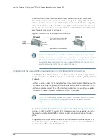
or modifiable. You can also interconnect EX4200 switches across distances of up to 25 miles
(40 km) by using the SFP, SFP+, or XFP uplink module ports. To do so, you must explicitly set
the uplink module ports on the members you want to connect as VCPs. See “Setting an Uplink
Module Port as a Virtual Chassis Port (CLI Procedure)” on page 1023. When you set the uplink
module ports as uplink VCPs and connect member switches through those uplink VCPs, a LAG
is automatically formed when the link speed is the same on connected VCPs and at least two
VCPs on one member are connected to at least two VCPs on another member. See
“Understanding Virtual Chassis Configurations and Link Aggregation” on page 932.
Virtual Chassis port (VCP)
interfaces
EX4200 switches have a VME interface. This is a logical interface that is used for Virtual Chassis
configurations and allows you to manage all the members of the Virtual Chassis through the
master. For more information on the VME interface, see “Understanding Global Management
of a Virtual Chassis Configuration” on page 929.
Virtual management Ethernet
(VME) interface
Related
Documentation
EX2200 Switches Hardware Overview on page 25
•
•
EX3200 and EX4200 Switches Hardware Overview on page 26
•
EX4500 Switches Hardware Overview on page 30
•
EX8208 Switch Hardware Overview on page 33
•
EX8216 Switch Hardware Overview on page 36
•
PoE and EX Series Switches Overview on page 3303
•
Understanding Aggregated Ethernet Interfaces and LACP on page 1099
•
Understanding Layer 3 Subinterfaces on page 1104
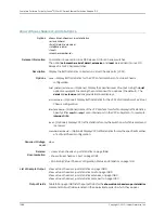
Understanding Interface Naming Conventions on EX Series Switches
Juniper Networks EX Series Ethernet Switches use a naming convention for defining the
interfaces that is similar to that of other platforms running under Juniper Networks Junos
operating system (Junos OS). This topic provides brief information on the naming
conventions used for interfaces on EX Series switches. For additional information, see
the
Junos OS Network Interfaces Configuration Guide
at
http://www.juniper.net/techpubs/software/junos/index.html
.
This topic describes:
•
Physical Part of an Interface Name on page 1098
•
Logical Part of an Interface Name on page 1099
•
Wildcard Characters in Interface Names on page 1099
1097
Copyright © 2010, Juniper Networks, Inc.
Chapter 50: Interfaces—Overview
Summary of Contents for JUNOS OS 10.3 - SOFTWARE
Page 325: ...CHAPTER 17 Operational Mode Commands for System Setup 229 Copyright 2010 Juniper Networks Inc ...
Page 1323: ...CHAPTER 56 Operational Mode Commands for Interfaces 1227 Copyright 2010 Juniper Networks Inc ...
Page 2841: ...CHAPTER 86 Operational Commands for 802 1X 2745 Copyright 2010 Juniper Networks Inc ...
Page 3367: ...CHAPTER 113 Operational Mode Commands for CoS 3271 Copyright 2010 Juniper Networks Inc ...
Page 3435: ...CHAPTER 120 Operational Mode Commands for PoE 3339 Copyright 2010 Juniper Networks Inc ...
Page 3529: ...CHAPTER 126 Operational Mode Commands for MPLS 3433 Copyright 2010 Juniper Networks Inc ...


