


Step-by-Step
Procedure
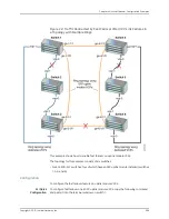
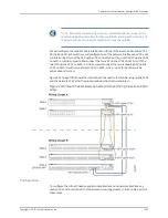
To configure a Virtual Chassis across multiple wiring closets and interconnect them to
form LAGs:
1.
Configure the mastership priority of SWA-0 (member
0
) to be the highest possible
value (
255
), thereby ensuring that it functions as the master of the expanded Virtual
Chassis configuration:
[edit virtual-chassis]
user@SWA-0#
set member 0
mastership-priority
255
2.
Power on SWA-1.
3.
Prepare the members in wiring closet A for interconnecting with the member
switches in wiring closet B by setting all of the SFP uplink module interfaces on
SWA-0 and two of the uplink module interfaces on SWA-1 as uplink VCPs:
user@SWA-0>
request virtual-chassis vc-port
set pic-slot 1 port 0
user@SWA-0>
request virtual-chassis vc-port set pic-slot 1 port 1
user@SWA-0>
request virtual-chassis vc-port set pic-slot 1 port 2
user@SWA-0>
request virtual-chassis vc-port set pic-slot 1 port 3
user@SWA-0>
request virtual-chassis vc-port set pic-slot 1 port 0 member 1
user@SWA-0>
request virtual-chassis vc-port set pic-slot 1 port 1 member 1
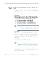
NOTE:
This example omits the specification of the member member-id
option in configuring the uplink VCPs for SWA-0 (and, later, for SWA-2).
The command applies by default to the switch where it is executed.
4.
Power on SWA-2.
5.
If SWA-2 was previously configured, revert to the factory default configuration.
6.
Prepare SWA-2 in wiring closet B by configuring its mastership priority to be the
highest possible value (255). Its member ID is currently
0
, because it is not yet
interconnected with the other members of the Virtual Chassis configuration. It is
operating as a standalone switch. Its member ID will change when it is
interconnected.
[edit virtual-chassis]
user@SWA-2#
set
member
0 mastership-priority 255
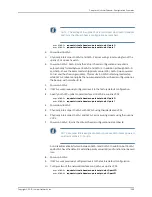
NOTE:
SWA-2 is configured with the same mastership priority value
that we configured for SWA-0. However, the longer uptime of SWA-0
ensures that, once the interconnection is made, SWA-0 functions as
the master and SWA-2 functions as the backup.
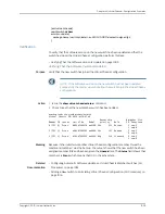
7.
Specify two of the SFP uplink module interfaces in SWA-2 as uplink VCPs. The
member IDs are
0
, because they are not yet interconnected with the other members
of the Virtual Chassis configuration:
Copyright © 2010, Juniper Networks, Inc.
1002
Complete Software Guide for Junos
®
OS for EX Series Ethernet Switches, Release 10.3
Summary of Contents for JUNOS OS 10.3 - SOFTWARE
Page 325: ...CHAPTER 17 Operational Mode Commands for System Setup 229 Copyright 2010 Juniper Networks Inc ...
Page 1323: ...CHAPTER 56 Operational Mode Commands for Interfaces 1227 Copyright 2010 Juniper Networks Inc ...
Page 2841: ...CHAPTER 86 Operational Commands for 802 1X 2745 Copyright 2010 Juniper Networks Inc ...
Page 3367: ...CHAPTER 113 Operational Mode Commands for CoS 3271 Copyright 2010 Juniper Networks Inc ...
Page 3435: ...CHAPTER 120 Operational Mode Commands for PoE 3339 Copyright 2010 Juniper Networks Inc ...
Page 3529: ...CHAPTER 126 Operational Mode Commands for MPLS 3433 Copyright 2010 Juniper Networks Inc ...


