


To set the uplink ports for the local member switch (for example, member 0) and for a
different member switch (for example, member 1) to function as VCPs:
1.
Set one uplink port of member 0 as a VCP interface. You do not need to specify the
member member-id
option, because the command applies by default on the member
where it is executed.
user@SWA-0>
request virtual-chassis vc-port
set pic-slot 1 port 0
2.
Set one uplink port of member 1 as a VCP interface.
user@SWA-0>
request virtual-chassis vc-port set pic-slot 1 port 0 member 1
This example includes the member
member-id
option, because it is executed on a
different member switch than the local member switch.
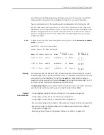
Setting an Uplink VCP on a Standalone Switch
To set an uplink VCP on a standalone switch, first power on the switch. You must set an
uplink port on the standalone switch as a VCP prior to physically interconnecting the
switch with the existing Virtual Chassis configuration. Otherwise, the master cannot
detect that the switch is a member of the Virtual Chassis configuration.
To set one uplink VCP on the potential member (SWA-2), which is currently operating
as a standalone switch:
1.
Power on the standalone switch.
2.
Set one uplink port as a VCP interface. You do not need to specify the
member
member-id
option, because the command applies by default on the member where
it is executed.
user@SWA-2>
request virtual-chassis vc-port
set pic-slot 1 port 0
NOTE:
If you do specify the member member-id option, use member ID 0.
Because the switch is not yet interconnected with the other members of
the Virtual Chassis configuration, its current member ID is 0. Its member
ID will change when it is interconnected with the Virtual Chassis
configuration. It does not impact the functioning of the uplink VCP that
its VCP interface is set with 0 as the member ID. The VCP interface has
significance only on the local switch.
3.
After you have set the uplink VCP on the standalone switch, physically interconnect
its uplink port with the VCP uplink ports of the members in the existing Virtual Chassis
configuration.
4.
The new member switch reboots and joins the now expanded Virtual Chassis
configuration with a different member ID.
1025
Copyright © 2010, Juniper Networks, Inc.
Chapter 45: Configuring Virtual Chassis
Summary of Contents for JUNOS OS 10.3 - SOFTWARE
Page 325: ...CHAPTER 17 Operational Mode Commands for System Setup 229 Copyright 2010 Juniper Networks Inc ...
Page 1323: ...CHAPTER 56 Operational Mode Commands for Interfaces 1227 Copyright 2010 Juniper Networks Inc ...
Page 2841: ...CHAPTER 86 Operational Commands for 802 1X 2745 Copyright 2010 Juniper Networks Inc ...
Page 3367: ...CHAPTER 113 Operational Mode Commands for CoS 3271 Copyright 2010 Juniper Networks Inc ...
Page 3435: ...CHAPTER 120 Operational Mode Commands for PoE 3339 Copyright 2010 Juniper Networks Inc ...
Page 3529: ...CHAPTER 126 Operational Mode Commands for MPLS 3433 Copyright 2010 Juniper Networks Inc ...


