175
Detail program description - Control adjust
Fine-tuning the throttle and collective pitch curve
Practical approach
Although the throttle and collective pitch control systems
are based on separate servos, they are always operated
together by the throttle/collective pitch stick (except
during auto-rotation fl ight). This coupling is performed by
the helicopter program automatically.
In the
mx-20
HoTT program, the trim lever of control
function 1 acts principally only on the throttle servo.
However, in the "
Stick mode
" menu (see page 94)
you can determine whether this should be used for idle
trimming as part of the throttle limit function, or for idle
trimming during the auto-rotation phase ("throttle AR").
The process of fi ne-tuning throttle and collective
pitch, i. e. setting the motor power curve to match the
collective blade pitch setting, is the most important
aspect of setting up a model helicopter. The
mx-20
HoTT software provides for independent confi guration
of the throttle, collective pitch and torque compensation
curves, in addition to the C1 control curve ("
Channel 1
curve
" menu, page 119).
While these curves can be modeled using up to
six points, fewer points are generally suffi cient. We
recommend starting with three-point curves to begin
with. This involves setting individual values for the center
point and other (optional) reference points, and for the
two end-points ("L", "low", and "H", "high") of the throttle/
collective pitch stick: together, these defi ne the control
curves.
Before setting the throttle and collective pitch function,
however, you should accurately calibrate the mechanical
linkages for all the servos, following the set-up
instructions for the helicopter in question.
Note:
The hover point should normally be set to the center
position of the throttle / collective pitch stick. For
some special cases, however, e. g. for "3D" fl ight,
you may wish to program hover points that deviate
from this standard. For example: one point for
normal fl ight attitude above the center and one point
for inverted fl ight attitude below the center.
Idle setting and throttle curve
Note:
Since electric drive systems have no need for an idle
setting, motor idling does not need to be calibrated.
Fine-tuning of the throttle and collective pitch curve(s),
however, must take place as for glow-powered helis.
The idle setting described in detail on pages 105 to
107 always takes place with the throttle limiter closed –
normally with the trim lever of the C1 function and only
in special cases is the throttle limiter itself also utilized
(as standard, the CTRL 6 proportional rotary control).
The programming of a corresponding value for the "L"
point of the throttle curve acts to set the descent speed
of the motor, without infl uencing the hover confi guration.
Here, for example, you can use fl ight phase
programming in order to confi gure a range of throttle
curves. This increased system rotational speed
below the hover point proves to be useful in certain
circumstances, for example for fast, steep landing
approaches with greatly reduced collective pitch, and for
aerobatics.
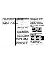
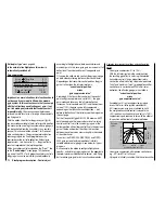
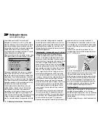
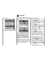
The screen image depicts a curve
with a slightly changeable throttle
setting below the hover point at
the control center.
Control travel
OUTPUT
Different throttle curves are programmed for each fl ight
phase, so that you can use the optimum set-up for both
hovering and aerobatics:
Low system rotational speed with smooth, gentle
•
control response and low noise when hovering
Higher rotor speed for aerobatics with motor power
•
set close to the maximum. In this case, the throttle
curve must also be adjusted in the hover range.
Basic set-up procedure
While the
mx-20
HoTT transmitter permits the
electronic confi guration of collective pitch curve and
throttle curves to a large degree, fi rst ensure that you
have correctly set all of the model's mechanical linkages
as specifi ed by the helicopter manual. Experienced
helicopter pilots will be glad to help you with this basic
set-up.
The carburetor linkage must be set so that the throttle is
just past the fully open setting with collective pitch set to
maximum or, for electric helis, with the speed controller
set to full. When the throttle limiter is closed, however,
it must be possible to just close off the carburetor using
the C1 trim lever (rapid throttle setting of the "digital
trim", see page 54), without the servo mechanically
striking its end-stop. For electric helis, it must be
possible to cut the electric motor's speed controller
safely with the throttle limiter closed.
Take great care when confi guring these settings, by
adjusting the control linkage as required and/or altering
the linkage point on the servo or carburetor lever. Only
then should you optimize throttle servo fi ne-tuning
electronically.
Caution:
Inform yourself thoroughly about the dangers and
Summary of Contents for mx-20 Hott
Page 41: ...41 Your notes...
Page 49: ...49 Your notes...
Page 55: ...55 Your notes...
Page 81: ...81 Your notes...
Page 85: ...85 Your notes...
Page 89: ...89 Your notes...
Page 99: ...99 Detail program description Control adjust...
Page 127: ...127 Detail program description Control adjust...
Page 131: ...131 Detail program description Control adjust...
Page 163: ...163 Detail program description Control adjust...
Page 191: ...191 Detail program description Control adjust...
Page 207: ...207 Detail program description Control adjust...
Page 228: ...228 Detail program description Control adjust...
Page 229: ...229 Detail program description Control adjust...
Page 251: ...251 Detail program description Control adjust...


