125
Detail program description - Control adjust
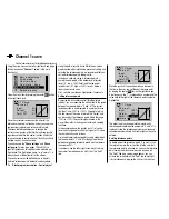
FIf a control switch – e. g. "C1" – has multiple
•
assignments, you should bear in mind that the
switching direction set here applies to all C3
switches.
The switch state can also be inverted by reversing
•
the control on the "
Control adjust
" menu.
Combining a control switch with one of the SW 1 …
9 switches
The control switch can be overridden by a further switch,
so that e. g. in certain fl ight situations the function to be
triggered can be activated independently of the control
position and thus the position of the control switch.
Switch to the value fi eld in the 5th column, the column
above the right switch icon. In the simplest case, select
one of the switches SW 1 … 9 as described under
"Assigning transmitter controls, switches and control
switches" on page 52. The number of this switch, e. g.
"2", appears on the display screen in the rightmost
column, together with a switch icon that indicates the
current state of the switch:
SEL
05%
05%
0%
C1
C2
C3
–––
C4
CONTROL SWITCH
Ct6
+85%
STO
2
–––
–––
While this switch is open, the "C1" control switch is
active, i. e. it triggers at the switching point; if the switch
is closed, the control switch now remains permanently
closed as well, independently of the control position and
switching direction:
SEL
0%
0%
0%
C1
C2
C3
–––
C4
CONTROL SWITCH
–75%
STO
2
–––
–––
Ct6
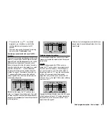
Combining two control switches
For more complex applications, however, it can prove
necessary to override this control switch with a second
control switch.
Example:
Instead of being assigned the CTRL 6 control as
before, the "C1" control switch is now assigned control
function 3 (transmitter control 3). The switching point
is at its center point, i.e. at 0%. The switch chosen in
the rightmost column is "C2", from the list of expanded
switches. We now assign one of the two center
proportional rotary controls to this control switch "C2",
on its own line – e. g. the right CTRL 8, whose switching
point lies at +50%:
SEL
0%
0%
+50%
C1
C2
C3
–––
C4
CONTROL SWITCH
STO
–––
–––
Ct3
C2
Ct8
0%
Reading the switching directions given in the 4th column
of the display, control switch "C3" remains closed while
the joystick (K3) and/or "transmitter control 9" is/are
beyond the switching point.
This diversity of switching options certainly offers you
enough scope for specialized applications to suit any
type of model.
Summary of Contents for mx-20 Hott
Page 41: ...41 Your notes...
Page 49: ...49 Your notes...
Page 55: ...55 Your notes...
Page 81: ...81 Your notes...
Page 85: ...85 Your notes...
Page 89: ...89 Your notes...
Page 99: ...99 Detail program description Control adjust...
Page 127: ...127 Detail program description Control adjust...
Page 131: ...131 Detail program description Control adjust...
Page 163: ...163 Detail program description Control adjust...
Page 191: ...191 Detail program description Control adjust...
Page 207: ...207 Detail program description Control adjust...
Page 228: ...228 Detail program description Control adjust...
Page 229: ...229 Detail program description Control adjust...
Page 251: ...251 Detail program description Control adjust...


