258
Detail program description - Control adjust
Here, select the menu item "Copy fl ight phase" with the
arrow keys and then briefl y press the central
SET
key of
the right touch pad.
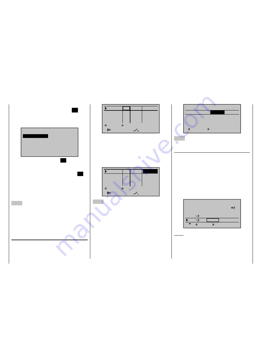
In the appearing window, "Copy from phase", "1 Normal"
is selected ...
7
Copy from phase:
3
5
=>
=>
2
4
6
1 Nor mal
Ther mal
Speed
Launch
… and then briefl y press the central
SET
key of the
right touch pad, whereby the display switches to
"Copy to phase". Now the target is selected (initially "2
Thermal") and confi rmed by pressing the central
SET
key of the right touch pad again. After confi rmation of
the subsequent safety query, all settings are copied
according to the selection.
Proceed in the same manner with the other two phases
("1 Normal" to "3 Speed" and "1 Normal" to "4 Start").
4. Step
Now three or four phases are programmed, the settings
are also copied and there is even a "soft" transfer, but ...
there are still no fl ight-phase specifi c settings.
Now, if applicable, in order to adapt the fl ap positions to
the different requirements of the individual fl ight phases,
in the menu ...
"Control adjust"
(page 96)
… the standard default "GL" is fi rst changed to "PH" for
"Phase" in the type column:
Input 5
offset
0%
0%
0%
–––
0%
Input 6
Input 7
Input 8
–––
–––
PH
GL
GL
GL
typ
Nor mal
–––
Then switch to the "Offset" column and make the
settings deviating from the "Normal" fl ight phase for the
ailerons. However, switch to the desired fl ight phase
beforehand, whose name is shown at the bottom in
the display, appropriate to the switch position. Both
positive and negative throw changes are possible. These
settings are to be made separately for each fl ight phase:
Input 5
offset
0%
0%
–––
0%
Input 6
Input 7
Input 8
–––
–––
PH
GL
GL
GL
typ
Nor mal
–––
–7%
5. Step
Any necessary phase-specifi c trimming of the elevator is
made with the help of the digital trimming of the elevator
joystick. This requires that you have at least set the
elevator trimming to "Phase" in the "
Joystick setting
"
menu - as already shown in this programming example.
Alternatively, you can also carry out these settings in the
"
Phase trim
" menu ...
Nor mal
0%
ELEV
Ther mal
0%
QR
Launch
Ther mal
Speed
0%
0%
0%
0%
0%
0%
6. Step
In the menu …
"Wing mixers"
(beginning on page 146)
… the fl ight phase name of the newly activated fl ight
phase appears at the bottom edge of the display. If
the switch position is now changed, the name of the
fl ight phase selected with the switch appears, but
with the previously copied settings of the fl ight phase
"Normal". Here you set you values phase-specifi cally
for the aileron differentiation, the share of the mixture
of transverse to side, and if applicable, also a mixture
of altitude to transverse. (The latter increases the agility
over the transverse axis when "Turning".)
Aile.diff.
Brake sttings
AI
55%
WING MIXERS
EL
FL
0%
0%
–––
–––
RU
Thermal
33%
Notice:
The list of displayed options depends on the number of
servos entered in the "Ailerons/fl aps" line in the "
Model
type
" menu.
Now switch to the submenu …
Summary of Contents for mx-20 Hott
Page 41: ...41 Your notes...
Page 49: ...49 Your notes...
Page 55: ...55 Your notes...
Page 81: ...81 Your notes...
Page 85: ...85 Your notes...
Page 89: ...89 Your notes...
Page 99: ...99 Detail program description Control adjust...
Page 127: ...127 Detail program description Control adjust...
Page 131: ...131 Detail program description Control adjust...
Page 163: ...163 Detail program description Control adjust...
Page 191: ...191 Detail program description Control adjust...
Page 207: ...207 Detail program description Control adjust...
Page 228: ...228 Detail program description Control adjust...
Page 229: ...229 Detail program description Control adjust...
Page 251: ...251 Detail program description Control adjust...


