218
Detail program description - Control adjust
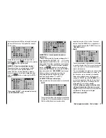
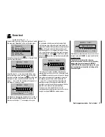
RX SERVO TEST
ALL–MIN : 1000
μ
sec
ALL–MAX : 2000
μ
sec
ALARM VOLT : 3.8V
ALARM TEMP–:–10°C
ALARM TEMP+: 70°C
TEST : START
CH OUTPUT TYPE:
SUMO
A HoTT receiver confi gured as SUMO permanently
generates a so-called sum signal from the control
signals of all of its control channels and provides this
by default to the accompanying GR-24 receiver at
servo connection 8.
On receivers whose display shows "SUMO" at the
top right, an additional two-digit number appears ...
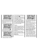
RX SERVO TEST
ALL–MIN : 1000
μ
sec
ALL–MAX : 2000
μ
sec
ALARM VOLT : 3.8V
ALARM TEMP–:–10°C
ALARM TEMP+: 70°C
TEST : START
CH OUT TYPE:
SUMO
08
… the active fi eld changes after confi rmation of
"SUMO" by briefl y pressing the central
SET
key
of the right touch pad for the channel selection.
With this selection you specify the
highest
of the
transmitter channels contained in the SUMO signal:
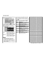
RX SERVO TEST
ALL–MIN : 1000
μ
sec
ALL–MAX : 2000
μ
sec
ALARM VOLT : 3.8V
ALARM TEMP–:–10°C
ALARM TEMP+: 70°C
TEST : START
CH OUT TYPE:SUMO
08
You can confi rm the default by pressing the
SET
key
of the right touch pad again or by selecting one of
the other channels between 04 and 06 with the arrow
keys and confi rming with
SET
.
The receiver outputs are controlled successively in a
cycle of 20 ms (30 ms with the receiver GR-24, Order
No.
33512,
), even if 10 ms is set in the "PERIOD" line
of the the "
RX SERVO
" display page.
Primarily intended for the "Satellite mode" of two
HoTT receivers, as described in the following, the
generated sum signal defi ned by the receiver as
SUMO can be used for the control of fl ight simulators;
this is also the case for the control of fl yable systems,
insofar as they have the corresponding input or the
adapter cable with Order No.
33310
.
In …
Satellite mode
… two HoTT receivers are connected to one another
through a three-wire connecting cable (Order No.
33700.1
(300 mm) or
33700.2
(100 mm)) at receiver-
type-specifi c servo connections. Receivers of the
type GR-16 and GR-24, for example, are to be
connected with one another at servo output 8. More
detailed information can be found on the internet at
www.graupner.de.
Through this connection, all channels of the HoTT
receiver which was confi gured as SUMO and
identifi ed as a satellite receiver are transmitted to the
second HoTT receiver, the main receiver, which is to
be programmed as ...
SUMI (sum signal IN)
•
Therefore, the signal always goes toward SUMI:
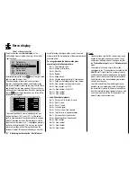
RX SERVO TEST
ALL–MIN : 1000
μ
sec
ALL–MAX : 2000
μ
sec
ALARM VOLT : 3.8V
ALARM TEMP–:–10°C
ALARM TEMP+: 70°C
TEST : START
CH OUT TYPE:
SUMI
The receiver defi ned as SUMI, however, only uses
the sum signal coming from SUMO in the event of
a failure of receipt if at least one channel in SUMI is
programmed to fail-safe.
If the receiver programmed as SUMO satellite
receiver has a failure of receipt, the servos connected
to this receiver assume the fail-safe positions
programmed in the satellite receiver completely
independently of the main receiver.
On the other hand, if a failure of receipt takes place
with two receivers
simultaneously,
the receiver
software current at the time of the printing of
this manual falls back on the fail-safe settings of
SUMO. In the individual case, however, interactions
cannot be ruled out,
which is why we urgently
recommend performing an appropriate test
BEFORE commissioning a model.
This receiver combination is recommended, if, for
example , one of the two receivers is installed in
the model at an unfavorable position for receiving
or as a result of nozzles, carbon fi ber material or
the like, there is the danger that the receipt signal
is weakened due to the fl ight position, so that
interruptions of the range must be taken into account.
Therefore, make sure to connect the most important
control functions to the main receiver programmed
as SUMI, so that, in the event of a failure, the model
Summary of Contents for mx-20 Hott
Page 41: ...41 Your notes...
Page 49: ...49 Your notes...
Page 55: ...55 Your notes...
Page 81: ...81 Your notes...
Page 85: ...85 Your notes...
Page 89: ...89 Your notes...
Page 99: ...99 Detail program description Control adjust...
Page 127: ...127 Detail program description Control adjust...
Page 131: ...131 Detail program description Control adjust...
Page 163: ...163 Detail program description Control adjust...
Page 191: ...191 Detail program description Control adjust...
Page 207: ...207 Detail program description Control adjust...
Page 228: ...228 Detail program description Control adjust...
Page 229: ...229 Detail program description Control adjust...
Page 251: ...251 Detail program description Control adjust...


