225
Detail program description - Control adjust
H - J S a n d b r u n n e r
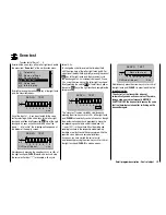
1
PPM10
SEL
BASIC SETTINGS
Own
Stick mode
DSC Output
Pitch min
back
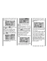
Briefl y press the
SET
key. The current stick mode is
shown inversely. Now, using the arrow keys of the
right touch pad, select the alternative you use most
frequently, from 1 to 4. In the future this will be used for
newly initialized model memories, but can be changed
on an individual basis for up to 24 model memories.
After simultaneously pressing the keys
or
of
the right touch pad (
CLEAR
), the display returns to stick
mode "1"
By pressing the
SET
key again, you deactivate the
selection fi eld in order to switch lines.
Winged model stick mode
“
MODE 2
” (Throttle at left stick)
“MODE 3”
(Throttle at right stick)
“MODE 4”
(Throttle at left stick)
“MODE 1”
(Throttle at right stick)
elev. down
elev. up
left r
udder
right r
udder
full throttle
idle
left aileron
right aileron
full throttle
left r
udder
right r
udder
idle
elev. down
elev. up
left aileron
right aileron
elev. down
elev. up
left aileron
right aileron
Motor Vollgas
idle
left r
udder
right r
udder
full throttle
idle
left aileron
right aileron
elev. down
elev. up
left r
udder
right r
udder
Helicopter model stick mode
“MODE 2”
(Throttle at left stick)
“MODE 3”
(Throttle at right stick)
“MODE 4”
(Throttle at left stick)
“MODE 1”
(Throttle at right stick)
pitch axis
tail rotor
pitch axis
tail rotor
throttle
roll
roll
throttle
tail rotor
tail rotor
throttle
throttle
pitch axis
pitch axis
roll
roll
pitch axis
pitch axis
roll
roll
Motor/Pitch
throttle
tail rotor
tail rotor
throttle
throttle
roll
roll
pitch axis
pitch axis
tail rotor
tail rotor
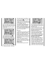
DSC Output (specifi cation)
In the line with the same name in the "
Base setup
model
" menu you can determine which of the three
available modulation types should be provided for the
DSC socket separately for each model memory. This
selection primarily infl uences the number of maximum
control channels available at the DSC socket and
thus for a fl ight simulator or LS system connected at
this socket. With the selection of "PPM10", this is the
channels 1 ... 5, with "PPM18" the channels 1 ... 9 and
with "PPM24" the control channels 1 ... 12.
SEL
99sec
DSC output
PPM10
RF Range Test
R12
R08
OFF
BASIC SETTINGS, MODEL
Rcv Ch Map
RF transmit
In
this
"General settings" menu, you can determine
which of the three possible "Modulation types" should
be adopted as the
default
to a newly initialized model
memory in the line "DSC Output" the same way as with
"Stick mode".
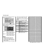
If necessary, using the arrow keys
of the left or
right touch pad, switch to the "DSC Output" line and, by
briefl y pressing the central
SET
key of the right touch
pad, activate the value window:
H - J S a n d b r u n n e r
1
SEL
BASIC SETTINGS
Own
Stick mode
DSC Output
Pitch min
back
PPM10
Now you case choose between the three possible
modulation types "PPM10", "PPM18" and "PPM24"
using the arrow keys of the right touch pad. By pressing
the central
SET
key of the right touch pad again, you
complete the entry.
Simultaneously pressing the keys
or
of the
right touch pad (
CLEAR
) returns to "PPM10".
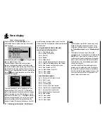
(Default) Pitch min
(only relevant for helicopter models)
Enter your preferred actuation direction for the throttle/
pitch joystick analogously to the "Stick mode" and "DSC
Output" options described above, in order to be able
to fi nd it for newly initialized model memories in the
future. The functions of all other options of the helicopter
program depend on this setting, insofar as they pertain to
the throttle and pitch function, in other words the throttle
curve, idle trim, Channel 1
tail rotor mixer, etc.
The following meanings apply:
"
front
": minimum front pitch setting, the pitch joystick
(C1) points away from the pilot.
Summary of Contents for mx-20 Hott
Page 41: ...41 Your notes...
Page 49: ...49 Your notes...
Page 55: ...55 Your notes...
Page 81: ...81 Your notes...
Page 85: ...85 Your notes...
Page 89: ...89 Your notes...
Page 99: ...99 Detail program description Control adjust...
Page 127: ...127 Detail program description Control adjust...
Page 131: ...131 Detail program description Control adjust...
Page 163: ...163 Detail program description Control adjust...
Page 191: ...191 Detail program description Control adjust...
Page 207: ...207 Detail program description Control adjust...
Page 228: ...228 Detail program description Control adjust...
Page 229: ...229 Detail program description Control adjust...
Page 251: ...251 Detail program description Control adjust...


