104
Detail program description - Control adjust
control using either the CTRL 7 or 8 proportional rotary
control.
"Thr.l 12"
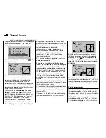
As standard, the "Thr.l 12" input is assigned to the CTRL
6 proportional rotary control mounted on the top left of
the transmitter.
Input 9
offset
0%
0%
0%
–––
0%
Input
Input
Th.L.12
Ct6
–––
–––
GL
GL
GL
GL
typ
Nor mal
10
11
This pre-assignment makes it unnecessary to program
the two fl ight phases that may be familiar to you from
using other remote control systems – namely "with
idle-up" and "without idle-up"" – ,since the
mx-20
HoTT program offers a much more fl exible approach to
fi ne-tuning and optimizing increases to system rotational
speed below the hover point than "idle-up". If you
nonetheless prefer to program your helicopter "with idle-
up", then deactivate the "throttle limit" function described
below by setting input "Thr.l 12" to "free".
Meaning and application of "throttle limit"
As already mentioned under "Throttle", and in contrast
to fi xed-wing models, the power output of a helicopter's
drive system is not controlled directly using the C1
joystick, but only indirectly via the throttle curve settings
on the
"Helicopter mixers"
menu or – if your model
features a speed
governor
– by using this mechanism.
Note:
For separate fl ight phases, you can of course use fl ight
phase programming to set specifi c throttle curves.
Nevertheless, both methods of output control de facto
result in the helicopter carburetor never approaching
Throttle limit function
anything near its idle speed under "normal" fl ight
conditions, and that the motor can therefore neither be
started or stopped cleanly without some other means of
intervention.
The "throttle limit" feature resolves this problem
elegantly by using a separate transmitter control – by
default the CTRL 6 proportional control mounted on the
top left of the transmitter – to
limit
the throttle servo or
the output level of the speed controller. In this way, it is
possible to use the throttle limit control to "throttle back"
as you wish as far as the idle setting – at which point
the trim lever on the throttle/collective pitch stick takes
over – or to cut out an electrical drive system directly.
Conversely, the throttle servo or speed controller can
only open up to its full-throttle position if the throttle limit
control has also released the full servo travel path.
The value set on the (right-hand) plus side of the "travel"
column must therefore always be set to high enough
to ensure that the maximum setting of the throttle limit
control never restricts the full-throttle position that can
be obtained using throttle curve settings – which typically
means setting a value in the range +100% to 125%.
–
+100%
+100%
+100%
+100%
+100%
+100%
+100%
Nor mal
Input 9
Input10
Input
Th.L.12
+125%
11
The value on the (left-hand) minus side of the "travel"
column should be set so that the throttle limit control
can be used to safely cut out an electrical drive system
or close a carburetor down far enough that the glow
motor can also be cut out in conjunction with the
Summary of Contents for mx-20 Hott
Page 41: ...41 Your notes...
Page 49: ...49 Your notes...
Page 55: ...55 Your notes...
Page 81: ...81 Your notes...
Page 85: ...85 Your notes...
Page 89: ...89 Your notes...
Page 99: ...99 Detail program description Control adjust...
Page 127: ...127 Detail program description Control adjust...
Page 131: ...131 Detail program description Control adjust...
Page 163: ...163 Detail program description Control adjust...
Page 191: ...191 Detail program description Control adjust...
Page 207: ...207 Detail program description Control adjust...
Page 228: ...228 Detail program description Control adjust...
Page 229: ...229 Detail program description Control adjust...
Page 251: ...251 Detail program description Control adjust...


