129
Detail program description - Control adjust
changes of phase, however, although it can be stopped
during any fl ight phase via the center
ESC
key on the
left touch pad.
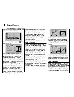
While you can obviously record lap times using "Lap"
and a switch (SW), the two timers "Time1" and "Time2"
have the following meaning:
Time1
Only the times are measured at which the switch
or control switch assigned in the "Lap timer/
timer" line of the "
Fl. phase timers
" menu (see
page 142) is "closed". The frequency at which
the switch is activated is shown on the basic
display. This counter fi eld is highlighted as soon
as the switch for the "Time1" timer is "opened",
i. e. the timer is stopped:
GRAUBELE
#01
2:22h
Stop
Flt
«Speed »
K78
0:00
0:00
5.5V
5.2V
0:00.0
M
Lap
00
If required, you can then use the arrow keys to
access and read the times at which switches
were made.
Application:
Measurement of e. g. motor switch-on times, if
the same switch also actuates the motor.
Time2
"Time2" stores both the "Off" and the "On" times
for the associated switch, i. e. each actuation of
the switch restarts the time count again and the
counter is incremented by "1".
Each time count can be stopped by using the
center
ESC
key on the right touch pad, without
activating the switch itself. Activating the switch,
in turn, increments the counter by 1 and restarts
the "Time2" timer.
In order to read out the time memory by using the
arrow keys, the "Time2" timer must fi rst be stopped
by using the
ESC
key on the right touch pad.
Application:
In addition to the motor runtimes, for example,
the unpowered glide times between these could
also be recorded.
Tapping the
or
keys on the right touch pad at
the same time (
CLEAR
) will reset the display of stopped
timers on the basic display.
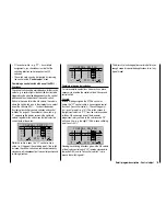
"Motor" column
Note:
This column is only available if "Forward/back" is
entered on the line "Motor on C1" on the "
Model type
"
menu.
Pha1
Pha2
Pha3
Name
motor
Pha4
Pha5
+
+
Nor mal
Launch
Dist.
–
–
yes
yes
yes
yes
yes
"Yes" The motor connected to receiver output 1 will
be controlled by the C1 joystick (throttle/brake
stick).
The brake system to be set up on the "
Wing
mixers
" menu is deactivated:
BRAKE SETTINGS
nor mal
Nor mal
off
"No"
The motor connected to receiver output 1
is decoupled from the C1 joystick (throttle/
brake stick) and is held in its OFF position – as
specifi ed by the setting "Throttle min. forward /
back" – automatically.
The brake system to be set up on the "
Wing
mixers
" menu is activated and is actuated by
the C1 joystick.
Elevat cur ve
BRAKE SETTINGS
AILE
Crow
D.red
0%
0%
0%
0%
0%
0%
WK
WK2
Nor mal
Note:
The settings available depend on the number of control
surface servos selected on the line "Ailerons/Camber-
changing fl aps in the "
Model type
" menu.
"Sw. time" column
When you switch between fl ight phases, it is advisable
to use this column to program a switch time for a "soft"
transition INTO (!) the respective phase. Accordingly,
there is also the option of specifying different times for
different switches – e. g. from a phase into Phase 3 and
the same phase into Phase 1.
Summary of Contents for mx-20 Hott
Page 41: ...41 Your notes...
Page 49: ...49 Your notes...
Page 55: ...55 Your notes...
Page 81: ...81 Your notes...
Page 85: ...85 Your notes...
Page 89: ...89 Your notes...
Page 99: ...99 Detail program description Control adjust...
Page 127: ...127 Detail program description Control adjust...
Page 131: ...131 Detail program description Control adjust...
Page 163: ...163 Detail program description Control adjust...
Page 191: ...191 Detail program description Control adjust...
Page 207: ...207 Detail program description Control adjust...
Page 228: ...228 Detail program description Control adjust...
Page 229: ...229 Detail program description Control adjust...
Page 251: ...251 Detail program description Control adjust...


