214
Detail program description - Control adjust
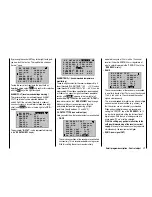
Therefore, the servo connections 6, 7 and 8 of a
receiver are mapped with one another, whereby the
OUTPUT CH (servo connections) 06, 07 and 08 are
assigned as INPUT CH of the same respective control
channel "04"...
RX FAIL SAFE
INPUT CH: 04
MODE : OFF
F.S.POS. : 1670
μ
sec
DELAY : 0.75sec
OUTPUT CH: 06
POSITION : 1670
μ
sec
FAIL SAFE ALL: NO
RX FAIL SAFE
INPUT CH: 04
MODE : OFF
F.S.POS. : 1230
μ
sec
DELAY : 0.75sec
OUTPUT CH: 07
POSITION : 1670
μ
sec
FAIL SAFE ALL: NO
RX FAIL SAFE
INPUT CH: 04
MODE : HOLD
F.S.POS. : 1770
μ
sec
DELAY : 0.75sec
OUTPUT CH: 08
POSITION : 1670
μ
sec
FAIL SAFE ALL: NO
… the INPUT CH 04 determines the fail-safe behavior of
these three servos connected to the control channel 4
completely independently of the individual settings of the
respective OUTPUT CH:
RX FAIL SAFE
INPUT CH: 04
MODE : FAI-SAFE
F.S.POS. : 1500
μ
sec
DELAY : 0.75sec
OUTPUT CH: 04
POSITION : 1500
μ
sec
FAIL SAFE ALL: NO
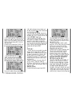
This is also the case, for example, if this is mapped with
INPUT CH 01:
RX FAIL SAFE
INPUT CH: 01
MODE : FAI-SAFE
F.S.POS. : 1500
μ
sec
DELAY : 0.75sec
OUTPUT CH: 04
POSITION : 1500
μ
sec
FAIL SAFE ALL: NO
In this case, the servo connection 04 would, in turn,
react according to the fail-safe settings of CH 01.
The reaction or delay time set in the "DELAY" line, on
the other hand, always applies uniformly for all channels
set to "FAI(L) SAFE".
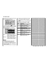
RX FREE MIXER
RX FREE MIXER
MASTER CH: 00
SLAVE CH : 00
S–TRAVEL–: 100
S–: 100
MIXER : 1
RX WING MIXER
TAIL TYPE: NORMAL
Value
Explanation
Possible settings
MIXER
Mixer selection
1, 2 or 3
Value
Explanation
Possible settings
MASTER CH Signal source or
source channel
0, 1 … depending
on receiver
SLAVE CH
Target channel
0, 1 … depending
on receiver
S-TRAVEL–
Admix negative
0 … 100 %
S-
Admix positive
0 … 100 %
RX WING
MIXER
Tail unit type
(TAIL TYPE)
NORMAL,
V-TAIL (V-LW)
ELEVON
(vertical/horizontal
mixer for delta and
fl ying wing)
MIXER
Up to three mixers can be programmed simultaneously.
Switch between Mixer 1, Mixer 2 and Mixer 3 through
"MIXER".
The following settings in this display
always
for just the
mixer selected in the "MIXER" line.
Important notice:
If you have already programmed mixer functions
in the "Wing mixer" or "Free mixer" menu, make
absolutely sure that these mixers do not overlap
with those in the menu "RX FREE MIXER"!
MASTER CH ("from")
According to the same principles described in the
section "Free mixer" on page 180, the signal applied
at the MASTER CH (signal source or source channel)
is mixed to a variable extent to the SLAVE CH (target
channel).
Select "00" if no mixer should be set.
Summary of Contents for mx-20 Hott
Page 41: ...41 Your notes...
Page 49: ...49 Your notes...
Page 55: ...55 Your notes...
Page 81: ...81 Your notes...
Page 85: ...85 Your notes...
Page 89: ...89 Your notes...
Page 99: ...99 Detail program description Control adjust...
Page 127: ...127 Detail program description Control adjust...
Page 131: ...131 Detail program description Control adjust...
Page 163: ...163 Detail program description Control adjust...
Page 191: ...191 Detail program description Control adjust...
Page 207: ...207 Detail program description Control adjust...
Page 228: ...228 Detail program description Control adjust...
Page 229: ...229 Detail program description Control adjust...
Page 251: ...251 Detail program description Control adjust...


