Index-6
2021 Carryall 300 Maintenance and Service Manual
INDEX
belt tension inspection ...................................... 19-14
brush spring
inspection ....................................................... 19-3
replacement ................................................... 19-3
brushes ............................................................. 19-2
inspection ....................................................... 19-3
replacement ................................................... 19-3
commutator........................................................ 19-5
armature replacement ..................................... 19-8
cleaning ......................................................... 19-8
inspection ....................................................... 19-8
disassembly ...............................................19-2, 19-5
field coil
inspection ..................................................... 19-10
removal .......................................................... 19-7
installation ....................................................... 19-13
removal ............................................................. 19-1
rework ............................................................. 19-10
testing ................................................... 18-22–18-23
adjustment ........................................................... 7-6
rack and pinion
assembly........................................................ 7-10
disassembly ..................................................... 7-8
installation ...................................................... 7-13
removal ............................................................ 7-7
assembly ............................................................. 7-3
disassembly ......................................................... 7-3
installation ........................................................... 7-5
removal ............................................................... 7-3
installation ........................................................... 7-2
removal ............................................................... 7-1
camber adjustment ............................................. 7-15
components ....................................................... 7-17
delta a-plate, installation .................................. 7-20
delta a-plate, removal...................................... 7-20
kingpin and steering spindle, installation ........... 7-20
kingpin and steering spindle, removal............... 7-17
leaf spring, installation ..................................... 7-17
leaf spring, removal......................................... 7-17
shock absorber, installation.............................. 7-20
shock absorber, removal.................................. 7-20
wheel bearings and hub, inspection.................. 7-21
wheel bearings and hub, installation ................. 7-21
wheel bearings and hub, removal..................... 7-21
lubrication .......................................................... 7-15
toe-in adjustment................................................ 7-16
wheel alignment ................................................. 7-15
installation ........................................................ 9-5
removal ............................................................ 9-2
inspection and removal...................................... 9-1
installation ........................................................ 9-2
T
test procedures, CDT connection...........................11-27
test procedures, charger
AC power and continuity test of AC circuit........... 15-30
battery condition using charger.......................... 15-30
battery voltage using multimeter ........................ 15-29
DC circuit continuity test ................................... 15-31
DC plug/receptacle ........................................... 15-29
on-charge battery voltage ................................. 15-30
output test........................................................ 15-31
test procedures, Excel with ERIC charging
15-amp fuse..................................................... 12-16
16-pin connector .............................................. 12-30
4-pin connector ................................................ 12-34
batteries/voltage check ..................................... 12-14
battery pack voltage (under load) ...................... 12-15
charge indicator light ........................................ 12-33
charger interlock............................................... 12-24
charger receptacle............................................ 12-29
Forward/Neutral/Reverse control (FNR) ............. 12-20
index of ........................................................... 12-12
key switch........................................................ 12-19
MCOR ............................................................. 12-25
MCOR limit switch ............................................ 12-19
motor, A1 and A2 voltage.................................. 12-28
pre-charge resistor ........................................... 12-22
reverse buzzer ................................................. 12-32
Run/Tow switch ................................................ 12-15
solenoid........................................................... 12-23
solenoid activating coil ...................................... 12-22
solenoid diode.................................................. 12-22
speed sensor, motor ......................................... 12-27
test procedures, gasoline vehicle
4-pin connector ................................................ 18-41
accelerator pedal limit switch (pedal-start)........... 18-16
battery ............................................................... 18-9
battery load test ............................................... 18-29
charging diode (key-start) ................................. 18-46
fuel gauge........................................................ 18-36
fuel level sending unit ....................................... 18-34
fuel pump......................................................... 18-31
fuses ................................................................18-11
ground cables .................................................. 18-13
headlight socket
voltage at ..................................................... 18-39
hour meter ....................................................... 18-37
iignition spark................................................... 18-27
key switch
engine kill circuit (pedal-start) ........................ 18-15
ON position (key-start) .................................. 18-42
START position (key-start) ............................. 18-42
starter circuit (pedal-start) .............................. 18-14
kill limit switch (pedal-start) ............................... 18-21
light switch ....................................................... 18-38
low oil warning light .......................................... 18-29
maintenance/operate switch (key-start).............. 18-45
maintenance/operate switch (pedal-start)........... 18-19
malfunction indicator light.................................. 18-29
Summary of Contents for Carryall 300 2021
Page 2: ......
Page 16: ......
Page 551: ...80 2018 by Kohler Co All rights reserved KohlerEngines com 17 690 15 Rev...
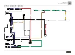
Page 565: ...GASOLINE ENGINE HARNESS Wiring Diagrams Gasoline Engine Harness 26...
Page 566: ...Page intentionally left blank...
Page 567: ...GASOLINE KEY START MAIN HARNESS Wiring Diagrams Gasoline Key Start Main Harness 26...
Page 568: ...Page intentionally left blank...
Page 569: ...GASOLINE PEDAL START MAIN HARNESS Wiring Diagrams Gasoline Pedal Start Main Harness 26...
Page 570: ...Page intentionally left blank...
Page 571: ...GASOLINE INSTRUMENT PANEL HARNESS Wiring Diagrams Gasoline Instrument Panel Harness 26...
Page 572: ...Page intentionally left blank...
Page 573: ...GASOLINE FNR HARNESS Wiring Diagrams Gasoline FNR Harness 26...
Page 574: ...Page intentionally left blank...
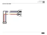
Page 575: ...ELECTRIC MAIN HARNESS Wiring Diagrams Electric Main Harness 26...
Page 576: ...Page intentionally left blank...
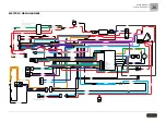
Page 577: ...ELECTRIC INSTRUMENT PANEL HARNESS Wiring Diagrams Electric Instrument Panel Harness 26...
Page 578: ...Page intentionally left blank...
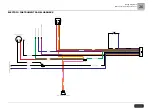
Page 579: ...ELECTRIC ACCESSORIES HARNESS Wiring Diagrams Electric Accessories Harness 26...
Page 580: ...Page intentionally left blank...
Page 588: ...NOTES...
Page 589: ...NOTES...
Page 590: ...NOTES...
Page 591: ...NOTES...
Page 592: ...NOTES...
Page 593: ...NOTES...
Page 594: ...NOTES...
Page 595: ......
Page 596: ......


