37
17 690 15 Rev. --
KohlerEngines.com
EFI SYSTEM
FUEL COMPONENTS
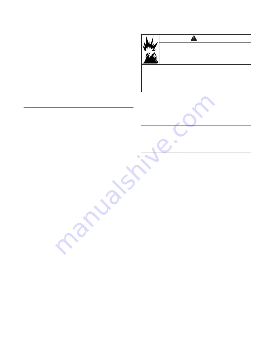
WARNING
Explosive Fuel can cause fi res and severe
burns.
Do not fi ll fuel tank while engine is hot or
running.
Gasoline is extremely fl ammable and its vapors can
explode if ignited. Store gasoline only in approved
containers, in well ventilated, unoccupied buildings,
away from sparks or fl ames. Spilled fuel could ignite if it
comes in contact with hot parts or sparks from ignition.
Never use gasoline as a cleaning agent.
NOTE: Engines in this application have in-tank fuel
pump, EFI fuel fi lter, and all fuel lines supplied
and installed by OEM. Refer to equipment
manufacturer's manual for information on these
components and before working on fuel system.
In-Tank Fuel Pump (OEM Supplied and Installed)
Refer to equipment manufacturer's manual for
information. Use only original equipment replacement
parts.
High Pressure Fuel Line (OEM Supplied and
Installed)
No specifi c servicing is required unless operating
conditions indicate that it needs replacement.
Thoroughly clean area around all joints and relieve
any pressure before starting any disassembly. Refer to
equipment manufacturer's manual for information. Use
only original equipment replacement parts.
Vent Hose Assembly (OEM Supplied and Installed)
Purge port is located on throttle body by TMAP
sensor and no specifi c servicing is required. No
specifi c servicing is required for vent hose assembly
(OEM supplied) unless operating conditions indicate
replacement is required. Use only original equipment
replacement parts. Visit KohlerEngines.com for
recommended Kohler replacement parts; refer to
equipment manufacturer's manual for replacement part
information.
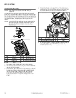
6. Pull retaining clip to separate fuel injector cap/
bracket assembly from injector. Remove screw
holding fuel injector cap/bracket assembly to throttle
body. Lift injector from throttle body.
7. Reverse appropriate procedures to install new
injector and reassemble engine. Use new O-ring and
retaining clip any time an injector is removed (new
replacement injector includes new O-rings and
retaining clip). Lubricate O-rings lightly with clean
engine oil. Use installation tool provided with O-rings
to install new upper O-ring. Place tool into fuel
injector inlet. Place one side of O-ring into O-ring
groove and roll O-ring over tool onto fuel injector.
Torque screw securing fuel injector cap to 7.3 N·m
(65 in. lb.). An ECU Reset and TPS Learn Procedure
will need to be completed.
Ignition Coil
If coil is determined to be faulty, replacement is
necessary. An ohmmeter may be used to test wiring and
coil windings.
NOTE: Do not ground coil with ignition ON as it may
overheat or spark.
NOTE: Always disconnect spark plug lead from spark
plug before performing following tests.
NOTE:
If ignition coil is disabled and an ignition
fault is registered, system will automatically
disable corresponding fuel injector drive
signal.
Fault must be corrected to ignition coil
and ECU power (switch) must be turned OFF for
15 seconds for injector signal to return. This is a
safety measure to prevent bore washing and oil
dilution.
Testing
Using an ohmmeter set on Rx1 scale, check resistance
in circuit as follows:
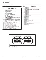
1. To check ignition coil, disconnect Black connector
from ECU and test between Black pins 1 and 15.
Wiring and coil primary circuit is OK if reading is
0.85-1.15
2. If reading is not within specifi ed range, check and
clean connections and retest.
3. If reading is still not within specifi ed range, test coil
separately from main harness as follows:
a. Remove mounting screw retaining coil and
disconnect primary lead connector.
b. Connect an ohmmeter set on Rx1 scale to
primary terminal of coil. Primary resistance
should be 0.5-0.8 Ω.
c. Connect an ohmmeter set on Rx10K scale
between spark plug boot terminal and B+ primary
terminal. Secondary resistance should be 6400-
7800 Ω.
d. If either primary or secondary resistance is not
within specifi ed range, coil is faulty and needs to
be replaced.
Summary of Contents for Carryall 300 2021
Page 2: ......
Page 16: ......
Page 551: ...80 2018 by Kohler Co All rights reserved KohlerEngines com 17 690 15 Rev...
Page 565: ...GASOLINE ENGINE HARNESS Wiring Diagrams Gasoline Engine Harness 26...
Page 566: ...Page intentionally left blank...
Page 567: ...GASOLINE KEY START MAIN HARNESS Wiring Diagrams Gasoline Key Start Main Harness 26...
Page 568: ...Page intentionally left blank...
Page 569: ...GASOLINE PEDAL START MAIN HARNESS Wiring Diagrams Gasoline Pedal Start Main Harness 26...
Page 570: ...Page intentionally left blank...
Page 571: ...GASOLINE INSTRUMENT PANEL HARNESS Wiring Diagrams Gasoline Instrument Panel Harness 26...
Page 572: ...Page intentionally left blank...
Page 573: ...GASOLINE FNR HARNESS Wiring Diagrams Gasoline FNR Harness 26...
Page 574: ...Page intentionally left blank...
Page 575: ...ELECTRIC MAIN HARNESS Wiring Diagrams Electric Main Harness 26...
Page 576: ...Page intentionally left blank...
Page 577: ...ELECTRIC INSTRUMENT PANEL HARNESS Wiring Diagrams Electric Instrument Panel Harness 26...
Page 578: ...Page intentionally left blank...
Page 579: ...ELECTRIC ACCESSORIES HARNESS Wiring Diagrams Electric Accessories Harness 26...
Page 580: ...Page intentionally left blank...
Page 588: ...NOTES...
Page 589: ...NOTES...
Page 590: ...NOTES...
Page 591: ...NOTES...
Page 592: ...NOTES...
Page 593: ...NOTES...
Page 594: ...NOTES...
Page 595: ......
Page 596: ......


