ELECTRIC VEHICLE - MOTOR
Motor Installation
16
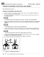
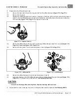
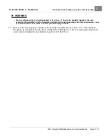
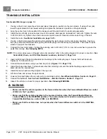
1
2
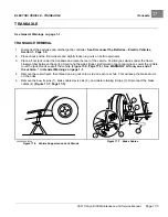
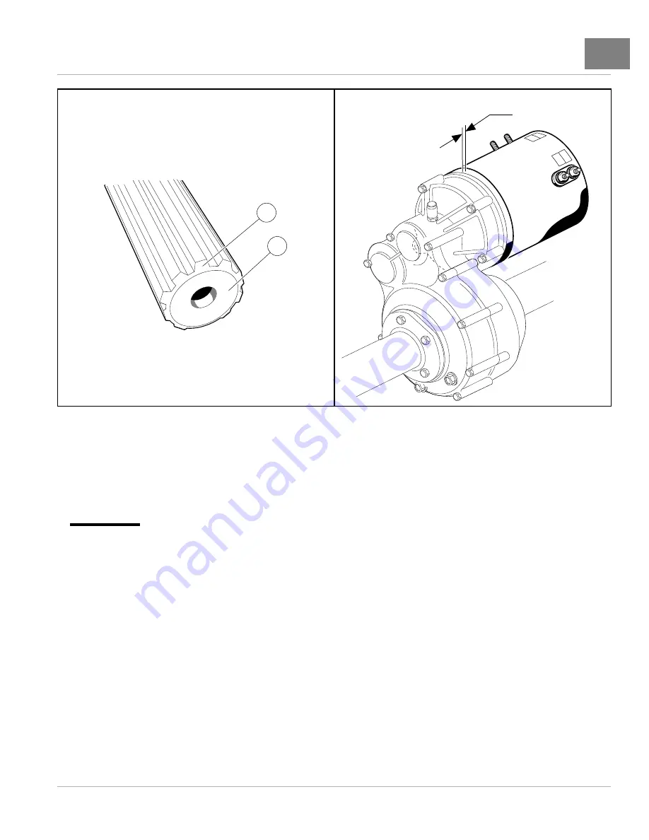
1/16 INCH (1.6 MM)
743
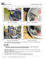
Figure 16-23
Clean Chamfer and Input Shaft End
744
Figure 16-24
Gap at Motor and Transaxle
4.2.
Loosely install the three bolts and lock washers that secure the motor to the transaxle
. Do not tighten.
4.3.
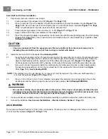
Begin finger-tightening the bolts (1, 2, and 3) in the sequence indicated. Continue tightening by hand until
the motor is seated in the transaxle housing.
See following CAUTION and NOTE.
CAUTION
• Make sure the motor is properly seated in the transaxle housing.
NOTE:
Failure to install and tighten the motor mounting bolts in the proper sequence and to the proper tightness may
result in motor noise during operation.
4.4.
Tighten the center bolt (3) to 100 in·lb (11.3 N·m).
4.5.
Tighten the left and right bolts (1 and 2) to 100 in·lb (11.3 N·m).
4.6.
Retighten all three bolts (1, 2, and 3) to 100 in·lb (11.3 N·m).
4.7.
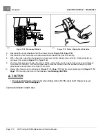
Install the motor wires, making sure they are connected to the correct motor terminals and that the terminal
orientation is correct.
See page 12-4.
Hold the bottom nut of stud with wrench and tighten the terminal
retaining nuts. For 5/16 inch (8mm) diameter studs, tighten the nuts to 100 in·lb (11 N·m). For 1/4 inch
(6.3mm) diameter studs, tighten the nuts to 45 in·lb (5.0 N·m).
4.8.
Secure the white, orange, green, and blue wires with a wire tie so that none of the motor wires will scrub the
motor or transaxle when the vehicle is in operation.
4.9.
Connect the three-pin speed sensor wire to the vehicle wire harness.
5.
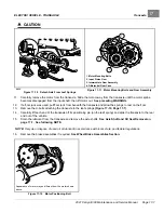
If using a chain hoist, lower the vehicle and guide the leaf springs into the shackles. If using a floor jack, raise the
transaxle until the leaf springs can be guided into the shackles.
2021 Carryall 300 Maintenance and Service Manual
Page 16-17
Summary of Contents for Carryall 300 2021
Page 2: ......
Page 16: ......
Page 551: ...80 2018 by Kohler Co All rights reserved KohlerEngines com 17 690 15 Rev...
Page 565: ...GASOLINE ENGINE HARNESS Wiring Diagrams Gasoline Engine Harness 26...
Page 566: ...Page intentionally left blank...
Page 567: ...GASOLINE KEY START MAIN HARNESS Wiring Diagrams Gasoline Key Start Main Harness 26...
Page 568: ...Page intentionally left blank...
Page 569: ...GASOLINE PEDAL START MAIN HARNESS Wiring Diagrams Gasoline Pedal Start Main Harness 26...
Page 570: ...Page intentionally left blank...
Page 571: ...GASOLINE INSTRUMENT PANEL HARNESS Wiring Diagrams Gasoline Instrument Panel Harness 26...
Page 572: ...Page intentionally left blank...
Page 573: ...GASOLINE FNR HARNESS Wiring Diagrams Gasoline FNR Harness 26...
Page 574: ...Page intentionally left blank...
Page 575: ...ELECTRIC MAIN HARNESS Wiring Diagrams Electric Main Harness 26...
Page 576: ...Page intentionally left blank...
Page 577: ...ELECTRIC INSTRUMENT PANEL HARNESS Wiring Diagrams Electric Instrument Panel Harness 26...
Page 578: ...Page intentionally left blank...
Page 579: ...ELECTRIC ACCESSORIES HARNESS Wiring Diagrams Electric Accessories Harness 26...
Page 580: ...Page intentionally left blank...
Page 588: ...NOTES...
Page 589: ...NOTES...
Page 590: ...NOTES...
Page 591: ...NOTES...
Page 592: ...NOTES...
Page 593: ...NOTES...
Page 594: ...NOTES...
Page 595: ......
Page 596: ......

