WHEEL BRAKE ASSEMBLIES
Brake Assembly Cleaning
6
BRAKE ASSEMBLY CLEANING
See General Warnings on page 1-1. See also Asbestos Dust Warning on page 6-1.
1.
Carefully clean the brake backing plate and all of its mechanical components.
2.
Remove the rubber boot from backing plate and wipe with a clean damp cloth.
3.
For vehicles equipped
without
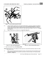
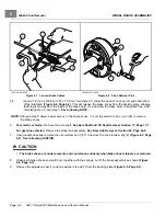
a slide plate (2), lubricate the backing plate, where the slide operates, with
dry moly lubricant.
4.
Lubricate the slide (1) with dry moly lubricant. After lubricating, work slide back and forth against backing plate to
ensure that it slides smoothly and easily. Install rubber boot onto backing plate.
WARNING
• Apply grease carefully when performing the following steps. Do not allow any grease to get onto
the friction surfaces of the brake shoe pads or the brake drum. Failure to adhere may could cause
diminished brake performance, possibly resulting in property damage or severe personal injury.
5.
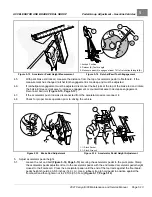
Use a small brush to carefully apply a light coat of white lithium NLGI #2 grease (Dow Corning
®
BR2-Plus or
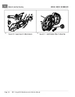
equivalent) on each of the six raised bosses on the brake backing plate
See preceding
WARNING.
6.
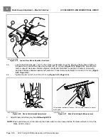
Use a small brush to carefully apply a light coat of white lithium NLGI #2 grease (Dow Corning BR2-Plus or
equivalent) to each end of both brake shoes and into the slots in the brake shoe mounting block as shown
.
See preceding WARNING.
640
Figure 6-8
Apply Grease On Bosses
641
Figure 6-9
Apply Grease To Brake Shoes and Slots
7.
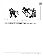
Use a small brush to carefully apply a light coat of white lithium NLGI #2 grease (Dow Corning BR2-Plus or
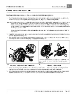
equivalent) to the brake adjuster assembly, adjuster wheel shoe slots, and the shaft of the adjuster wheel as
shown
.
See preceding WARNING.
8.
Install the adjuster wheel (1) and two washers (2 and 3) into the adjuster assembly
2021 Carryall 300 Maintenance and Service Manual
Page 6-5
Summary of Contents for Carryall 300 2021
Page 2: ......
Page 16: ......
Page 551: ...80 2018 by Kohler Co All rights reserved KohlerEngines com 17 690 15 Rev...
Page 565: ...GASOLINE ENGINE HARNESS Wiring Diagrams Gasoline Engine Harness 26...
Page 566: ...Page intentionally left blank...
Page 567: ...GASOLINE KEY START MAIN HARNESS Wiring Diagrams Gasoline Key Start Main Harness 26...
Page 568: ...Page intentionally left blank...
Page 569: ...GASOLINE PEDAL START MAIN HARNESS Wiring Diagrams Gasoline Pedal Start Main Harness 26...
Page 570: ...Page intentionally left blank...
Page 571: ...GASOLINE INSTRUMENT PANEL HARNESS Wiring Diagrams Gasoline Instrument Panel Harness 26...
Page 572: ...Page intentionally left blank...
Page 573: ...GASOLINE FNR HARNESS Wiring Diagrams Gasoline FNR Harness 26...
Page 574: ...Page intentionally left blank...
Page 575: ...ELECTRIC MAIN HARNESS Wiring Diagrams Electric Main Harness 26...
Page 576: ...Page intentionally left blank...
Page 577: ...ELECTRIC INSTRUMENT PANEL HARNESS Wiring Diagrams Electric Instrument Panel Harness 26...
Page 578: ...Page intentionally left blank...
Page 579: ...ELECTRIC ACCESSORIES HARNESS Wiring Diagrams Electric Accessories Harness 26...
Page 580: ...Page intentionally left blank...
Page 588: ...NOTES...
Page 589: ...NOTES...
Page 590: ...NOTES...
Page 591: ...NOTES...
Page 592: ...NOTES...
Page 593: ...NOTES...
Page 594: ...NOTES...
Page 595: ......
Page 596: ......

