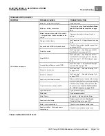


ELECTRIC VEHICLE - ELECTRICAL SYSTEM
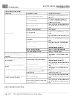
TROUBLESHOOTING
Test Procedures
12
5.2.
If pre-charge resistor test is good reinstall.
6.
Place the Run/Tow switch in the TOW position and connect the batteries.
See Connect the Batteries – Electric
TEST PROCEDURE 9 – Solenoid Continuity
See General Warnings on page 1-1.
Solenoid Continuity Test with the CDT Handset
1.
If necessary, see Testing Basics on page 12-12.
2.
Place chocks at the front wheels and lift the rear of the vehicle with a chain hoist or floor jack. Position jack
stands under the frame rails just forward of each spring mount.
See WARNING “Lift only one end...” in
3.
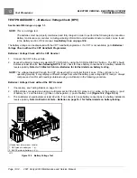
Connect the CDT to the vehicle.
4.
Access the Monitor menu and select MAIN CONT DRIVER by using the SCROLL DISPLAY buttons. The
CDT should indicate OFF.
5.
Turn the key switch to the ON position and place the Forward/Neutral/Reverse control (FNR) in the F position.
6.
Press the accelerator pedal. When the controller energizes the solenoid coil, the CDT should indicate ON. If not,
check the KEY, FORWARD, REVERSE and FOOT INPUTS to the controller.
See Sonic Weld, Diode, and 10k
Ohm Resistor Locations on page 12-4.
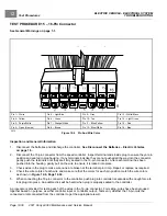
Also check the 16-pin connector at the speed controller.
See Test
Procedure 15 – 16-Pin Connector on page 12-30.
7.
If the CDT displays readings other than those described above and the wiring is found to be correct, go to the
following procedure,
Solenoid Continuity Test without the CDT Handset
.
Solenoid Continuity Test without the CDT Handset
1.
If necessary, see Testing Basics on page 12-12.
2.
Place chocks at the front wheels and lift the rear of the vehicle with a chain hoist or floor jack. Position jack
stands under the frame rails just forward of each spring mount.
See WARNING “Lift only one end...” in
3.
Disconnect the batteries and discharge the controller.
See Disconnect the Batteries – Electric Vehicles
4.
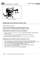
Disconnect the 6-gauge yellow wire and pre-charge resistor from large post of solenoid.
See following NOTE.
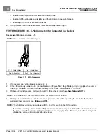
NOTE:
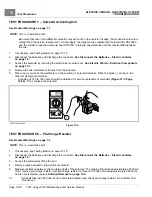
When disconnecting heavy gauge wires from solenoid, use a second wrench on the lower nut of the terminal
post to hold post steady, preventing damage to the solenoid.
If the pre-charge resistor is not disconnected, the meter will read approximately 250 ohms.
5.
Check for continuity between the two large posts of the solenoid. The reading should be no continuity. If continuity
is found, the solenoid has failed CLOSED and must be replace.
See Solenoid Removal on page 13-6.
6.
Reconnect the 6-gauge yellow wire and pre-charge resistor to the solenoid and secure with washer and nut.
Tighten nut to 77 in·lb (8.7 N·m).
7.
Place the Run/Tow switch in the TOW position and connect the batteries.
See Connect the Batteries – Electric
WARNING
• Keep people and equipment clear from rotating rear wheels. Do not allow persons under the car.
Contact with rotating rear wheels could result in serious personal injury.
8.
Change the multimeter to measure resistance.
2021 Carryall 300 Maintenance and Service Manual
Page 12-23
Summary of Contents for Carryall 300 2021
Page 2: ......
Page 16: ......
Page 551: ...80 2018 by Kohler Co All rights reserved KohlerEngines com 17 690 15 Rev...
Page 565: ...GASOLINE ENGINE HARNESS Wiring Diagrams Gasoline Engine Harness 26...
Page 566: ...Page intentionally left blank...
Page 567: ...GASOLINE KEY START MAIN HARNESS Wiring Diagrams Gasoline Key Start Main Harness 26...
Page 568: ...Page intentionally left blank...
Page 569: ...GASOLINE PEDAL START MAIN HARNESS Wiring Diagrams Gasoline Pedal Start Main Harness 26...
Page 570: ...Page intentionally left blank...
Page 571: ...GASOLINE INSTRUMENT PANEL HARNESS Wiring Diagrams Gasoline Instrument Panel Harness 26...
Page 572: ...Page intentionally left blank...
Page 573: ...GASOLINE FNR HARNESS Wiring Diagrams Gasoline FNR Harness 26...
Page 574: ...Page intentionally left blank...
Page 575: ...ELECTRIC MAIN HARNESS Wiring Diagrams Electric Main Harness 26...
Page 576: ...Page intentionally left blank...
Page 577: ...ELECTRIC INSTRUMENT PANEL HARNESS Wiring Diagrams Electric Instrument Panel Harness 26...
Page 578: ...Page intentionally left blank...
Page 579: ...ELECTRIC ACCESSORIES HARNESS Wiring Diagrams Electric Accessories Harness 26...
Page 580: ...Page intentionally left blank...
Page 588: ...NOTES...
Page 589: ...NOTES...
Page 590: ...NOTES...
Page 591: ...NOTES...
Page 592: ...NOTES...
Page 593: ...NOTES...
Page 594: ...NOTES...
Page 595: ......
Page 596: ......


