12
Test Procedures
ELECTRIC VEHICLE - ELECTRICAL SYSTEM
TROUBLESHOOTING
TEST PROCEDURE 1 – Batteries / Voltage Check (BPV)
See General Warnings on page 1-1.
NOTE:
This is a voltage test.
The batteries must be properly maintained and fully charged in order to perform the following test procedures.
Battery maintenance procedures, including watering information and allowable mineral content, can be found
in the Battery section of this manual.
See Battery Care on page 14-6.
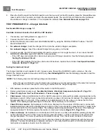
The battery voltage can be displayed with the CDT handheld programmer. If a CDT is not available, go to
Batteries /
Voltage Check without the CDT Handheld Programmer
.
Batteries / Voltage Check with the CDT Handset
1.
Connect the CDT to the vehicle.
2.
Access the Monitor menu and select BATT VOLTAGE by using the SCROLL DISPLAY buttons. The CDT should
indicate at least 48 volts.
See following NOTE.
If not, check for loose battery connections or a battery installed in
reverse polarity.
Refer to 14
for further details on battery testing.
NOTE:
The voltage displayed through the CDT shows what the controller thinks it sees. If the controller is not
operating properly, it may display a different voltage from what the battery pack voltage (BPV) really is. Always
compare and confirm with readings obtained using a multimeter in the following procedure.
Batteries / Voltage Check without the CDT Handset
1.
If necessary, see Testing Basics on page 12-12.
2.
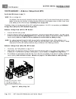
With batteries connected and using a multimeter set to 200 volts DC, place red (+) probe on the positive (+) post
of battery no. 1 and the black (–) probe on the negative (–) post of battery no.6
3.
The multimeter should indicate at least 48 volts. If not, check for loose battery connections or a battery installed in
reverse polarity.
Refer to Electric Vehicle - Batteries on page 14-1 for further details on battery testing.
2m
20
m
200
m
2k
200
200
200
200
20
2
200
m
500
20k
200k
2000
k
1000
OFF
WAVETEK
5XL
V
V
V
A
!
!
COM
200nA
MAX
1000 ---
750V
FUSED
(Viewed from driver side of vehicle)
1. RED probe to battery no. 1 (+).
2. BLACK probe to battery no. 6 (-).
2975
Figure 12-2
Battery Voltage Test
Page 12-14
2021 Carryall 300 Maintenance and Service Manual
Summary of Contents for Carryall 300 2021
Page 2: ......
Page 16: ......
Page 551: ...80 2018 by Kohler Co All rights reserved KohlerEngines com 17 690 15 Rev...
Page 565: ...GASOLINE ENGINE HARNESS Wiring Diagrams Gasoline Engine Harness 26...
Page 566: ...Page intentionally left blank...
Page 567: ...GASOLINE KEY START MAIN HARNESS Wiring Diagrams Gasoline Key Start Main Harness 26...
Page 568: ...Page intentionally left blank...
Page 569: ...GASOLINE PEDAL START MAIN HARNESS Wiring Diagrams Gasoline Pedal Start Main Harness 26...
Page 570: ...Page intentionally left blank...
Page 571: ...GASOLINE INSTRUMENT PANEL HARNESS Wiring Diagrams Gasoline Instrument Panel Harness 26...
Page 572: ...Page intentionally left blank...
Page 573: ...GASOLINE FNR HARNESS Wiring Diagrams Gasoline FNR Harness 26...
Page 574: ...Page intentionally left blank...
Page 575: ...ELECTRIC MAIN HARNESS Wiring Diagrams Electric Main Harness 26...
Page 576: ...Page intentionally left blank...
Page 577: ...ELECTRIC INSTRUMENT PANEL HARNESS Wiring Diagrams Electric Instrument Panel Harness 26...
Page 578: ...Page intentionally left blank...
Page 579: ...ELECTRIC ACCESSORIES HARNESS Wiring Diagrams Electric Accessories Harness 26...
Page 580: ...Page intentionally left blank...
Page 588: ...NOTES...
Page 589: ...NOTES...
Page 590: ...NOTES...
Page 591: ...NOTES...
Page 592: ...NOTES...
Page 593: ...NOTES...
Page 594: ...NOTES...
Page 595: ......
Page 596: ......


