24
Transaxle Installation
GASOLINE VEHICLE - TRANSAXLE
TRANSAXLE INSTALLATION
See General Warnings on page 1-1.
1.
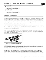
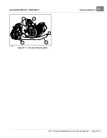
Installation is reverse of removal procedure. When attaching transaxle to powertrain, initially install the eight bolts
(1) finger-tight
. Then, tighten fasteners in the following order:
1.1.
Tighten the two bolts (1) at clutch plate (3) to 50 ft·lb (68 N·m).
1.2.
Tighten the four bolts (1) at engine pan (2) to 50 ft·lb (68 N·m).
1.3.
Tighten the two bolts (1) at muffler bracket to 50 ft·lb (68 N·m).
1.4.
Tighten the governor cable bracket (2) and FNR/accelerator cable bracket (2) bolts to 50 ft·lb (68 N·m)
.
1.5.
Tighten leaf spring hardware to 19 ft·lb (26 N·m) at chassis and shackle.
See Rear Suspension section.
1.6.
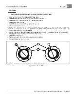
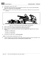
Tighten lower nuts of shock absorbers until cushions expand to be the same diameter as the mounting
washers.
1.7.
Tighten transaxle drain plug to 17 ft·lb (23.5 N·m).
2.
Fill transaxle with appropriate type and volume of oil.
See Oil Change – Transaxle on page 24-2.
3.
Ensure that all wires and cables are secured properly with wire ties.
See following WARNING.
WARNING
• If wires and cables are removed or replaced make sure they are properly routed and secured to vehicle
frame. Failure to properly route and secure wires and cables could result in vehicle malfunction,
property damage or personal injury.
4.
Connect battery and spark plug wire.
See Connect the Battery- Gasoline Vehicles on page 1-4.
5.
Check governor adjustment and correct if necessary.
See Governor Cable Installation and Adjustment,
6.
Check engine RPM setting. Adjust if necessary.
See Engine RPM Adjustment, Section 21, Page 21-10.
SHIFTER CABLE
See General Warnings on page 1-1.
If the Forward/Neutral/Reverse control (FNR) cable is damaged in any way, it must be replaced.
SHIFTER CABLE REMOVAL
NOTE:
Before removing cable, note cable routing and positions of wire ties or other devices securing the cable to the
vehicle. When installed, cable must be routed and secured as it was originally.
1.
Turn the key switch to the OFF position and remove the key. Place the Forward/Neutral/Reverse control (FNR) in
the NEUTRAL position and chock the wheels.
2.
Disconnect battery and spark plug wire.
See Disconnect the Battery- Gasoline Vehicles on page 1-4.
3.
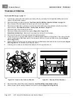
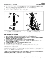
Push the cable end socket (1) off the stud (3) on the Forward/Neutral/Reverse control (FNR) handle
4.
Press in tangs (4) anchoring shifter cable (2) to chassis and push out of mounting hole.
Page 24-14
2021 Carryall 300 Maintenance and Service Manual
Summary of Contents for Carryall 300 2021
Page 2: ......
Page 16: ......
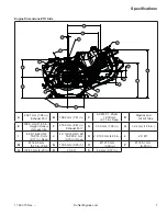
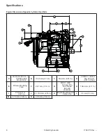
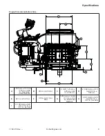
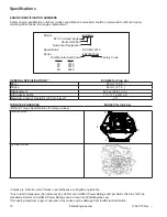
Page 551: ...80 2018 by Kohler Co All rights reserved KohlerEngines com 17 690 15 Rev...
Page 565: ...GASOLINE ENGINE HARNESS Wiring Diagrams Gasoline Engine Harness 26...
Page 566: ...Page intentionally left blank...
Page 567: ...GASOLINE KEY START MAIN HARNESS Wiring Diagrams Gasoline Key Start Main Harness 26...
Page 568: ...Page intentionally left blank...
Page 569: ...GASOLINE PEDAL START MAIN HARNESS Wiring Diagrams Gasoline Pedal Start Main Harness 26...
Page 570: ...Page intentionally left blank...
Page 571: ...GASOLINE INSTRUMENT PANEL HARNESS Wiring Diagrams Gasoline Instrument Panel Harness 26...
Page 572: ...Page intentionally left blank...
Page 573: ...GASOLINE FNR HARNESS Wiring Diagrams Gasoline FNR Harness 26...
Page 574: ...Page intentionally left blank...
Page 575: ...ELECTRIC MAIN HARNESS Wiring Diagrams Electric Main Harness 26...
Page 576: ...Page intentionally left blank...
Page 577: ...ELECTRIC INSTRUMENT PANEL HARNESS Wiring Diagrams Electric Instrument Panel Harness 26...
Page 578: ...Page intentionally left blank...
Page 579: ...ELECTRIC ACCESSORIES HARNESS Wiring Diagrams Electric Accessories Harness 26...
Page 580: ...Page intentionally left blank...
Page 588: ...NOTES...
Page 589: ...NOTES...
Page 590: ...NOTES...
Page 591: ...NOTES...
Page 592: ...NOTES...
Page 593: ...NOTES...
Page 594: ...NOTES...
Page 595: ......
Page 596: ......


