


ELECTRIC VEHICLE - ELECTRICAL SYSTEM
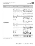
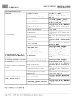
TROUBLESHOOTING
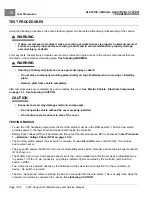
Test Procedures
12
3.2.
Place the Forward/Neutral/Reverse control (FNR) in the F position. The CDT should indicate that
FORWARD INPUT is ON. If the CDT indicates any other reading, check vehicle wiring.
Diode, and 10k Ohm Resistor Locations on page 12-4.
Also check the 16-pin connector at the speed
controller.
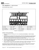
See Test Procedure 15 – 16-Pin Connector on page 12-30.
4.
Test REVERSE INPUT.
4.1.
Access the Monitor menu and select REVERSE INPUT by using the SCROLL DISPLAY buttons. The CDT
should indicate OFF when the Forward/Neutral/Reverse control (FNR) is in the NEUTRAL or F position.
4.2.
Place the Forward/Neutral/Reverse control (FNR) in the REVERSE position. The CDT should indicate that
REVERSE INPUT is ON. If the CDT indicates any other reading, check vehicle wiring.
Diode, and 10k Ohm Resistor Locations on page 12-4.
Also check the 16-pin connector at the speed
controller.
See Test Procedure 15 – 16-Pin Connector on page 12-30.
5.
If the CDT displays readings other than those described above and the wiring is found to be correct, go to the
following procedure,
Forward/Neutral/Reverse control (FNR) Test without the CDT Handset
.
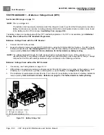
Forward/Neutral/Reverse control (FNR) Test without the CDT Handset
1.
If necessary, see Testing Basics on page 12-12.
2.
Place the Run/Tow switch in the RUN position and the Forward/Neutral/Reverse control (FNR) in the NEUTRAL
position.
3.
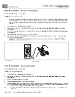
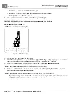
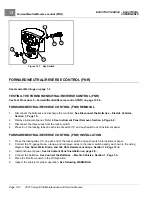
Remove Forward/Neutral/Reverse control (FNR) from its housing by carefully prying up each side with a small,
flat-tip screwdriver.
4.
Back-probe the following three wires connected to the Forward/Neutral/Reverse control (FNR) in each position:
4.1.
Orange Wire
– The orange wire provides power to the switch and should show BPV coming to the switch in all three
positions.
If the orange wire does not show BPV, check the 20–amp fuse, Run/Tow switch, red-to-pink wire spade
terminal connection and related wiring.
4.2.
Brown Wire
– The brown wire should show BPV in F.
– The brown wire should show zero (0) volts in NEUTRAL and REVERSE
If the brown wire shows voltage in NEUTRAL, the switch may have corrosion across the contacts or the
switch has failed CLOSED and must be replaced.
Forward/Neutral/Reverse control (FNR) Removal
.
If the brown wire does not show BPV in F, the switch may have corrosion on the contact or the switch has
failed OPEN and must be replaced.
Forward/Neutral/Reverse control (FNR) Removal
.
4.3.
Red/Green Wire
– The red/green wire should show BPV in REVERSE.
– The red/green wire should show zero (0) volts in NEUTRAL and F.
If the red/green wire shows voltage in NEUTRAL, the switch may have corrosion across the contacts or the
switch has failed CLOSED and must be replaced.
Forward/Neutral/Reverse control (FNR) Removal
.
If the red/green wire does not show BPV in REVERSE, the switch may have corrosion on the contact or the
switch has failed OPEN and must be replaced.
Forward/Neutral/Reverse control (FNR) Removal
.
2021 Carryall 300 Maintenance and Service Manual
Page 12-21
Summary of Contents for Carryall 300 2021
Page 2: ......
Page 16: ......
Page 551: ...80 2018 by Kohler Co All rights reserved KohlerEngines com 17 690 15 Rev...
Page 565: ...GASOLINE ENGINE HARNESS Wiring Diagrams Gasoline Engine Harness 26...
Page 566: ...Page intentionally left blank...
Page 567: ...GASOLINE KEY START MAIN HARNESS Wiring Diagrams Gasoline Key Start Main Harness 26...
Page 568: ...Page intentionally left blank...
Page 569: ...GASOLINE PEDAL START MAIN HARNESS Wiring Diagrams Gasoline Pedal Start Main Harness 26...
Page 570: ...Page intentionally left blank...
Page 571: ...GASOLINE INSTRUMENT PANEL HARNESS Wiring Diagrams Gasoline Instrument Panel Harness 26...
Page 572: ...Page intentionally left blank...
Page 573: ...GASOLINE FNR HARNESS Wiring Diagrams Gasoline FNR Harness 26...
Page 574: ...Page intentionally left blank...
Page 575: ...ELECTRIC MAIN HARNESS Wiring Diagrams Electric Main Harness 26...
Page 576: ...Page intentionally left blank...
Page 577: ...ELECTRIC INSTRUMENT PANEL HARNESS Wiring Diagrams Electric Instrument Panel Harness 26...
Page 578: ...Page intentionally left blank...
Page 579: ...ELECTRIC ACCESSORIES HARNESS Wiring Diagrams Electric Accessories Harness 26...
Page 580: ...Page intentionally left blank...
Page 588: ...NOTES...
Page 589: ...NOTES...
Page 590: ...NOTES...
Page 591: ...NOTES...
Page 592: ...NOTES...
Page 593: ...NOTES...
Page 594: ...NOTES...
Page 595: ......
Page 596: ......


