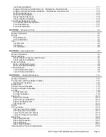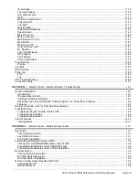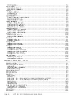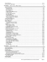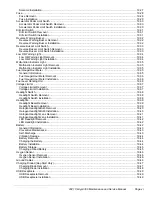
Axle Shaft ............................................................................................................................................... 17-1
Axle Bearing............................................................................................................................................ 17-4
Transaxle Disassembly and Inspection...................................................................................................... 17-8
Transaxle Assembly................................................................................................................................17-10
Accessories............................................................................................................................................. 18-1
Low Oil Warning Light .............................................................................................................................. 18-1
Malfunction Indicator Light........................................................................................................................ 18-2
Ground Locations .................................................................................................................................... 18-3
Features of the Electronic Fuel Injection (EFI) System ............................................................................... 18-3
Electrical System ......................................................................................................................................... 18-6
Test Procedures .......................................................................................................................................... 18-7
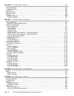
Starter/Generator Removal ...................................................................................................................... 19-1
Disassembly of the Starter/Generator to Service the Brushes ..................................................................... 19-2
Brush Inspection and Replacement........................................................................................................... 19-3
Brush Spring Inspection and Replacement ................................................................................................ 19-3
Starter/Generator Assembly ..................................................................................................................... 19-4
Disassembly of the Starter/Generator to Service the Armature/Commutator ................................................ 19-5
Bearing Cleaning and Inspection .............................................................................................................. 19-6
Bearing Removal ..................................................................................................................................... 19-7
Field Coil Assembly ................................................................................................................................. 19-7
Visual Inspection of Armature ................................................................................................................... 19-7
Commutator Cleaning and Inspection ....................................................................................................... 19-8
Armature Ground Test.............................................................................................................................. 19-9
Visual Inspection of Field Coils ................................................................................................................19-10
Starter/Generator Rework .......................................................................................................................19-10
Starter/Generator Assembly ....................................................................................................................19-10
Starter/Generator Installation...................................................................................................................19-13
Belt Tension Inspection For EFI Engines ..................................................................................................19-14
Belt Tension Adjustment for EFI Engines ..................................................................................................19-15
Belt Tension Tool Modification..................................................................................................................19-18
Key Switch Removal ...............................................................................................................................19-20
Key Switch Installation ............................................................................................................................19-21
Neutral Lockout Limit Switch Removal .....................................................................................................19-23
Neutral Lockout Limit Switch Installation...................................................................................................19-25
Page x
2021 Carryall 300 Maintenance and Service Manual
Summary of Contents for Carryall 300 2021
Page 2: ......
Page 16: ......
Page 551: ...80 2018 by Kohler Co All rights reserved KohlerEngines com 17 690 15 Rev...
Page 565: ...GASOLINE ENGINE HARNESS Wiring Diagrams Gasoline Engine Harness 26...
Page 566: ...Page intentionally left blank...
Page 567: ...GASOLINE KEY START MAIN HARNESS Wiring Diagrams Gasoline Key Start Main Harness 26...
Page 568: ...Page intentionally left blank...
Page 569: ...GASOLINE PEDAL START MAIN HARNESS Wiring Diagrams Gasoline Pedal Start Main Harness 26...
Page 570: ...Page intentionally left blank...
Page 571: ...GASOLINE INSTRUMENT PANEL HARNESS Wiring Diagrams Gasoline Instrument Panel Harness 26...
Page 572: ...Page intentionally left blank...
Page 573: ...GASOLINE FNR HARNESS Wiring Diagrams Gasoline FNR Harness 26...
Page 574: ...Page intentionally left blank...
Page 575: ...ELECTRIC MAIN HARNESS Wiring Diagrams Electric Main Harness 26...
Page 576: ...Page intentionally left blank...
Page 577: ...ELECTRIC INSTRUMENT PANEL HARNESS Wiring Diagrams Electric Instrument Panel Harness 26...
Page 578: ...Page intentionally left blank...
Page 579: ...ELECTRIC ACCESSORIES HARNESS Wiring Diagrams Electric Accessories Harness 26...
Page 580: ...Page intentionally left blank...
Page 588: ...NOTES...
Page 589: ...NOTES...
Page 590: ...NOTES...
Page 591: ...NOTES...
Page 592: ...NOTES...
Page 593: ...NOTES...
Page 594: ...NOTES...
Page 595: ......
Page 596: ......

