


GASOLINE VEHICLE - TROUBLESHOOTING
AND ELECTRICAL SYSTEM
Troubleshooting Guide
18
_
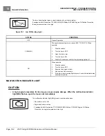
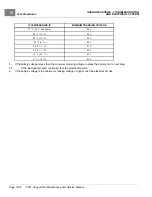
STATUS
CONDITION
OFF
Normal Operation
ON (for three seconds)
Normal Operation when the key switch is set to ON.
FLASHING
The engine temperature is at or above 283.1°F (139.5°C). When
possible:
1.
Stop the vehicle.
2.
Turn the key to OFF.
3.
Open the louver arm.
4.
Turn the key to ON.
5.
Wait for 15 minutes or until the MIL is off.
ON
The engine has sensed a fault. See the Kohler Engine Service Manual
for more information.
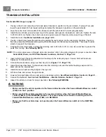
GROUND LOCATIONS
Electrical grounds are located at the following areas:
•
Below the Battery:
The battery, starter/generator, voltage regulator and main wire harness are all grounded to the
chassis on the frame rail below the battery.
•
In Front of Engine:
The engine is grounded to the chassis cross-member with an un-insulated, braided wire.
•
Top of Fuel Tank:
The fuel tank is grounded to the chassis through the main wire harness.
FEATURES OF THE ELECTRONIC FUEL INJECTION (EFI) SYSTEM
• Closed-loop system, oxygen (O2) sensor included
• Controls fuel pump, fuel injector, malfunction indicator light (MIL)
• Inputs: Temperature/Manifold Absolute Pressure (TMAP), Throttle Position Sensor (TPS), oxygen (O2) sensor,
crank sensor, ignition timing, cylinder head temp
• Separate EFI wire harness
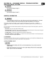
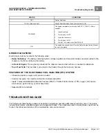
TROUBLESHOOTING GUIDE
The following troubleshooting guides will be helpful in identifying operating difficulties should they occur. The guides
include the symptom, probable cause(s) and suggested checks. The procedures used in making these checks can be
found in the referenced sections of the maintenance and service manual.
2021 Carryall 300 Maintenance and Service Manual
Page 18-3
Summary of Contents for Carryall 300 2021
Page 2: ......
Page 16: ......
Page 551: ...80 2018 by Kohler Co All rights reserved KohlerEngines com 17 690 15 Rev...
Page 565: ...GASOLINE ENGINE HARNESS Wiring Diagrams Gasoline Engine Harness 26...
Page 566: ...Page intentionally left blank...
Page 567: ...GASOLINE KEY START MAIN HARNESS Wiring Diagrams Gasoline Key Start Main Harness 26...
Page 568: ...Page intentionally left blank...
Page 569: ...GASOLINE PEDAL START MAIN HARNESS Wiring Diagrams Gasoline Pedal Start Main Harness 26...
Page 570: ...Page intentionally left blank...
Page 571: ...GASOLINE INSTRUMENT PANEL HARNESS Wiring Diagrams Gasoline Instrument Panel Harness 26...
Page 572: ...Page intentionally left blank...
Page 573: ...GASOLINE FNR HARNESS Wiring Diagrams Gasoline FNR Harness 26...
Page 574: ...Page intentionally left blank...
Page 575: ...ELECTRIC MAIN HARNESS Wiring Diagrams Electric Main Harness 26...
Page 576: ...Page intentionally left blank...
Page 577: ...ELECTRIC INSTRUMENT PANEL HARNESS Wiring Diagrams Electric Instrument Panel Harness 26...
Page 578: ...Page intentionally left blank...
Page 579: ...ELECTRIC ACCESSORIES HARNESS Wiring Diagrams Electric Accessories Harness 26...
Page 580: ...Page intentionally left blank...
Page 588: ...NOTES...
Page 589: ...NOTES...
Page 590: ...NOTES...
Page 591: ...NOTES...
Page 592: ...NOTES...
Page 593: ...NOTES...
Page 594: ...NOTES...
Page 595: ......
Page 596: ......


