


GASOLINE VEHICLE - TROUBLESHOOTING
AND ELECTRICAL SYSTEM
Test Procedures
18
TEST PROCEDURES
Using the following procedures, the entire electrical system can be tested without major disassembly of the vehicle.
WARNING
• If wires are removed or replaced, make sure wiring and wire harness is properly routed and secured.
Failure to properly route and secure wiring could result in vehicle malfunction, property damage,
personal injury, or death.
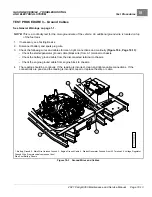
For some tests, the electrical component box cover must be removed to gain access to the various components that
are mounted inside the component box.
See following WARNING.
WARNING
• Shorting of battery terminals can cause personal injury or death.
After test procedures are completed, be sure to replace the cover.
See following CAUTION.
CAUTION
• Exposure to water and the elements may damage electrical components. Do not operate vehicle
without the cover properly installed.
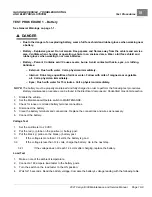
TESTING BASICS
• Battery voltage will be referenced throughout the test procedures. Battery voltage is accessed in the Battery test
procedure.
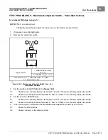
• The Maintenace/Operate switch, in the MAINTENANCE position, grounds and kills the ignition if the
Forward/Neutral/Reverse control (FNR) is placed in F or R.
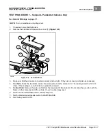
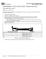
• The key switch powers the ECU, fuel pump, solenoid, lights, and the connected car device.
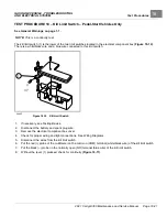
• The 2-amp fuse is powered by the key switch via the 10-amp ATM fuse and carries battery voltage to the connected
car device.
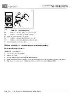
• The term “back-probe” refers to probing the side of a connector that the wire enters. This is usually done when
the connector must remain connected to a device. An alternative method is to use an insulation-piercing probe.
See following CAUTION.
CAUTION
• Be careful not to damage the wire or terminal when back-probing.
• When testing voltage, the battery must remain connected.
• When testing voltage, unless specifically directed to do otherwise in a procedure, connect the black (–) probe of the
multimeter to chassis ground.
• When testing resistance or continuity, turn off power to the circuit being measured and discharge any capacitor(s).
The presence of voltage can cause inaccurate readings.
Index of Test Procedures
2021 Carryall 300 Maintenance and Service Manual
Page 18-7
Summary of Contents for Carryall 300 2021
Page 2: ......
Page 16: ......
Page 551: ...80 2018 by Kohler Co All rights reserved KohlerEngines com 17 690 15 Rev...
Page 565: ...GASOLINE ENGINE HARNESS Wiring Diagrams Gasoline Engine Harness 26...
Page 566: ...Page intentionally left blank...
Page 567: ...GASOLINE KEY START MAIN HARNESS Wiring Diagrams Gasoline Key Start Main Harness 26...
Page 568: ...Page intentionally left blank...
Page 569: ...GASOLINE PEDAL START MAIN HARNESS Wiring Diagrams Gasoline Pedal Start Main Harness 26...
Page 570: ...Page intentionally left blank...
Page 571: ...GASOLINE INSTRUMENT PANEL HARNESS Wiring Diagrams Gasoline Instrument Panel Harness 26...
Page 572: ...Page intentionally left blank...
Page 573: ...GASOLINE FNR HARNESS Wiring Diagrams Gasoline FNR Harness 26...
Page 574: ...Page intentionally left blank...
Page 575: ...ELECTRIC MAIN HARNESS Wiring Diagrams Electric Main Harness 26...
Page 576: ...Page intentionally left blank...
Page 577: ...ELECTRIC INSTRUMENT PANEL HARNESS Wiring Diagrams Electric Instrument Panel Harness 26...
Page 578: ...Page intentionally left blank...
Page 579: ...ELECTRIC ACCESSORIES HARNESS Wiring Diagrams Electric Accessories Harness 26...
Page 580: ...Page intentionally left blank...
Page 588: ...NOTES...
Page 589: ...NOTES...
Page 590: ...NOTES...
Page 591: ...NOTES...
Page 592: ...NOTES...
Page 593: ...NOTES...
Page 594: ...NOTES...
Page 595: ......
Page 596: ......


