66
Disassembly/Inspection and Service
KohlerEngines.com
17 690 15 Rev. --
Inspection and Service
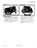
Dimension A
A
Cam Lobe
INTAKE
32.286 mm
(1.271 in.)
32.032 mm
(1.261 in.)
EXHAUST
32.506 mm
(1.280 in.)
32.252 mm
(1.270 in.)
Dimension B
B
Cam Lobe Specifi cations
Valve
Dimension B Service Limit
INTAKE
25.94 mm
(1.021 in.)
25.68 mm
(1.011 in.)
EXHAUST
25.94 mm
(1.021 in.)
25.68 mm
(1.011 in.)
Dimension C
C
Camshaft Journal Specifi cations
Dimension C
Limit
15.975 mm (0.6289 in.)
15.900 mm
(0.6260 in.)
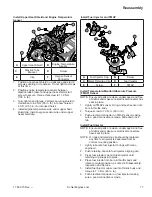
Inspect gear teeth of camshaft. If teeth are badly
worn, chipped, or some are missing, replacement of
camshaft will be necessary. If unusual wear or damage
is evident on either lobe or mating tappet, camshaft and
both tappets must be replaced. Check condition and
operation of ACR mechanism.
Measure cam lobe profi le, A and B, using an outside
micrometer and compare with specifi cations listed.
Measure camshaft journals, C, which fi t in ball
bearings, for wear using a micrometer. Compare with
specifi cations listed.
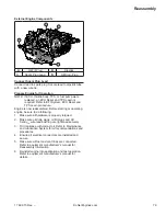
Remove Piston, Connecting Rod and Crankshaft
NOTE: If a carbon ridge is present at top of cylinder
bore, use a ridge reamer to remove it before
attempting to remove piston.
1. Remove screws securing end cap to connecting rod.
Remove end cap. Carefully guiding connecting rod,
slide piston and connecting rod from cylinder bore.
2. Remove crankshaft from crankcase.
Connecting Rod Inspection and Service
Check bearing area (big end) for excessive wear, score
marks, running and side clearances (see Specifi cations
and Tolerances). Replace rod and cap if scored or
excessively worn.
Service replacement connecting rods are available in
STD size and 0.25 mm (0.010 in.) undersize. 0.25 mm
(0.010 in.) undersized rods have an identifi cation
marking on lower end of rod shank. Always refer
to appropriate parts information to ensure correct
replacements are used.
Summary of Contents for Carryall 300 2021
Page 2: ......
Page 16: ......
Page 551: ...80 2018 by Kohler Co All rights reserved KohlerEngines com 17 690 15 Rev...
Page 565: ...GASOLINE ENGINE HARNESS Wiring Diagrams Gasoline Engine Harness 26...
Page 566: ...Page intentionally left blank...
Page 567: ...GASOLINE KEY START MAIN HARNESS Wiring Diagrams Gasoline Key Start Main Harness 26...
Page 568: ...Page intentionally left blank...
Page 569: ...GASOLINE PEDAL START MAIN HARNESS Wiring Diagrams Gasoline Pedal Start Main Harness 26...
Page 570: ...Page intentionally left blank...
Page 571: ...GASOLINE INSTRUMENT PANEL HARNESS Wiring Diagrams Gasoline Instrument Panel Harness 26...
Page 572: ...Page intentionally left blank...
Page 573: ...GASOLINE FNR HARNESS Wiring Diagrams Gasoline FNR Harness 26...
Page 574: ...Page intentionally left blank...
Page 575: ...ELECTRIC MAIN HARNESS Wiring Diagrams Electric Main Harness 26...
Page 576: ...Page intentionally left blank...
Page 577: ...ELECTRIC INSTRUMENT PANEL HARNESS Wiring Diagrams Electric Instrument Panel Harness 26...
Page 578: ...Page intentionally left blank...
Page 579: ...ELECTRIC ACCESSORIES HARNESS Wiring Diagrams Electric Accessories Harness 26...
Page 580: ...Page intentionally left blank...
Page 588: ...NOTES...
Page 589: ...NOTES...
Page 590: ...NOTES...
Page 591: ...NOTES...
Page 592: ...NOTES...
Page 593: ...NOTES...
Page 594: ...NOTES...
Page 595: ......
Page 596: ......

