


12
Test Procedures
ELECTRIC VEHICLE - ELECTRICAL SYSTEM
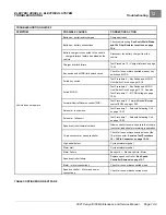
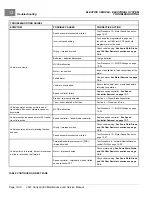
TROUBLESHOOTING
TEST PROCEDURES
Using the following procedures, the entire electrical system can be tested without major disassembly of the vehicle.
WARNING
• If wires are removed or replaced, make sure wiring and wire harness is properly routed and secured.
Failure to properly route and secure wiring could result in vehicle malfunction, property damage,
personal injury, or death.
For many tests, the electronics module cover must be removed to gain access to the various components that are
mounted on the component mounting plate.
See following WARNING.
WARNING
• Shorting of battery terminals can cause personal injury or death.
– Do not place component mounting plate directly on top of batteries when removing or installing
plate.
– Remove plate from vehicle completely.
After test procedures are completed, be sure to replace the cover.
See Electric Vehicle - Electrical Components
on page 13-1. See following CAUTION.
CAUTION
• Exposure to water may damage electronic components.
– Do not operate vehicle without the cover properly installed.
– Do not direct a water stream in area of the cover.
TESTING BASICS
• To use the CDT handheld programmer, the Run/Tow switch must be in the RUN position. The Run/Tow switch
provides power to the logic board and power board inside the controller.
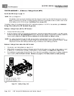
• Battery Pack Voltage (BPV) will be referenced throughout the test procedures. BPV is accessed in
1 – Batteries / Voltage Check (BPV) on page 12-14
• The Run/Tow switch powers the key switch, controller, Forward/Neutral/Reverse control (FNR), 15-amp fuse,
and reverse buzzer.
• The key switch powers the MCOR 2-pin circuit, Forward/Reverse switch, solenoid, and the female bullet connector
(W34 shown on .
• The MCOR 3-pin circuit, motor speed sensor circuit, the communication point for the car device (white/black wire
in position 13 of the 16 pin connector), and charge indicator light is powered by the controller (with Run/Tow
switch in RUN).
• The 2-amp fuse is powered directly by the batteries via the solenoid and carries BPV to the connected car
device. No switch is involved.
• The term “back-probe” refers to probing the side of a connector that the wire enters. This is usually done when the
connector must remain connected to a device.
See following CAUTION.
Page 12-12
2021 Carryall 300 Maintenance and Service Manual
Summary of Contents for Carryall 300 2021
Page 2: ......
Page 16: ......
Page 551: ...80 2018 by Kohler Co All rights reserved KohlerEngines com 17 690 15 Rev...
Page 565: ...GASOLINE ENGINE HARNESS Wiring Diagrams Gasoline Engine Harness 26...
Page 566: ...Page intentionally left blank...
Page 567: ...GASOLINE KEY START MAIN HARNESS Wiring Diagrams Gasoline Key Start Main Harness 26...
Page 568: ...Page intentionally left blank...
Page 569: ...GASOLINE PEDAL START MAIN HARNESS Wiring Diagrams Gasoline Pedal Start Main Harness 26...
Page 570: ...Page intentionally left blank...
Page 571: ...GASOLINE INSTRUMENT PANEL HARNESS Wiring Diagrams Gasoline Instrument Panel Harness 26...
Page 572: ...Page intentionally left blank...
Page 573: ...GASOLINE FNR HARNESS Wiring Diagrams Gasoline FNR Harness 26...
Page 574: ...Page intentionally left blank...
Page 575: ...ELECTRIC MAIN HARNESS Wiring Diagrams Electric Main Harness 26...
Page 576: ...Page intentionally left blank...
Page 577: ...ELECTRIC INSTRUMENT PANEL HARNESS Wiring Diagrams Electric Instrument Panel Harness 26...
Page 578: ...Page intentionally left blank...
Page 579: ...ELECTRIC ACCESSORIES HARNESS Wiring Diagrams Electric Accessories Harness 26...
Page 580: ...Page intentionally left blank...
Page 588: ...NOTES...
Page 589: ...NOTES...
Page 590: ...NOTES...
Page 591: ...NOTES...
Page 592: ...NOTES...
Page 593: ...NOTES...
Page 594: ...NOTES...
Page 595: ......
Page 596: ......


