


WHEEL BRAKE ASSEMBLIES
Brake Shoe Installation
6
BRAKE SHOE INSTALLATION
See General Warnings on page 1-1. See also Asbestos Dust Warning on page 6-1.
1.
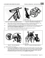
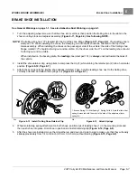
Turn the adjusting wheel screw so that the shoe slot is vertical, then position the trailing shoe in the slots in the
shoe mounting block and adjuster assembly
See following NOTE.
NOTE:
The trailing shoe has 17T stamped into the tip of the shoe flange
. The leading shoe is
stamped 17L. When installing the shoes, the stamping on both shoes should be oriented to the top of the
brake assembly. When installing the shoes on the passenger side of the vehicle, the side of the trailing shoe
flange marked 17T should be facing out and be visible. On the driver side, the 17L on the leading shoe should
be facing out and be visible.
When installed on the backing plate, the
leading
shoe (stamped 17L) is
always
oriented toward the
rear
of
the vehicle.
2.
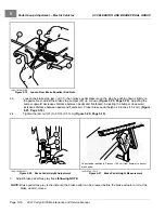
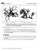
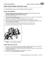
Install the shoe retainer clip, using pliers to compress the clip (1) while turning the retainer pin (2) into a horizontal
position
.
3.
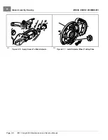
Attach the springs onto the trailing shoe already installed. Then, hold the leading shoe next to the trailing shoe,
correctly oriented, and attach the springs to it
.
4
1
2
3
1. Bronze Spring 2. Silver Spring 3. Spring Coils 4. Note that the silver
spring is mounted with the coils to the side of the adjustment lever
spring (A).
644
Figure 6-12
Install Trailing Shoe Retainer Clip
645
Figure 6-13
Attach Springs
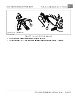
4.
While maintaining spring attachment on both shoes, position tips of leading shoe (1) in the mounting slots and
then push shoe into place. Hold shoe in position and install retaining clip
5.
After the shoes are installed, move them together up and down and side to side to make sure that they will easily
slide approximately from 1/4 to 3/8 inch (6.3 mm to 9.5 mm) without binding
.
2021 Carryall 300 Maintenance and Service Manual
Page 6-7
Summary of Contents for Carryall 300 2021
Page 2: ......
Page 16: ......
Page 551: ...80 2018 by Kohler Co All rights reserved KohlerEngines com 17 690 15 Rev...
Page 565: ...GASOLINE ENGINE HARNESS Wiring Diagrams Gasoline Engine Harness 26...
Page 566: ...Page intentionally left blank...
Page 567: ...GASOLINE KEY START MAIN HARNESS Wiring Diagrams Gasoline Key Start Main Harness 26...
Page 568: ...Page intentionally left blank...
Page 569: ...GASOLINE PEDAL START MAIN HARNESS Wiring Diagrams Gasoline Pedal Start Main Harness 26...
Page 570: ...Page intentionally left blank...
Page 571: ...GASOLINE INSTRUMENT PANEL HARNESS Wiring Diagrams Gasoline Instrument Panel Harness 26...
Page 572: ...Page intentionally left blank...
Page 573: ...GASOLINE FNR HARNESS Wiring Diagrams Gasoline FNR Harness 26...
Page 574: ...Page intentionally left blank...
Page 575: ...ELECTRIC MAIN HARNESS Wiring Diagrams Electric Main Harness 26...
Page 576: ...Page intentionally left blank...
Page 577: ...ELECTRIC INSTRUMENT PANEL HARNESS Wiring Diagrams Electric Instrument Panel Harness 26...
Page 578: ...Page intentionally left blank...
Page 579: ...ELECTRIC ACCESSORIES HARNESS Wiring Diagrams Electric Accessories Harness 26...
Page 580: ...Page intentionally left blank...
Page 588: ...NOTES...
Page 589: ...NOTES...
Page 590: ...NOTES...
Page 591: ...NOTES...
Page 592: ...NOTES...
Page 593: ...NOTES...
Page 594: ...NOTES...
Page 595: ......
Page 596: ......


