


EFI SYSTEM
26
17 690 15 Rev. --
KohlerEngines.com
Purpose of sensing air temperature is to help ECU
calculate air density. Higher air temperature less dense
air becomes. As air becomes less dense ECU knows
that it needs to lessen fuel fl ow to achieve correct air/fuel
ratio. If fuel fl ow was not changed engine would become
rich, possibly losing power and consuming more fuel.
Manifold Absolute Pressure check provides immediate
manifold pressure information to ECU. TMAP sensor
measures diff erence in pressure between outside
atmosphere and vacuum level inside intake passage
and monitors pressure in passage as primary means
of detecting load. Data is used to calculate air density
and determine engine's mass air fl ow rate, which in turn
determines required ideal fueling. TMAP also stores
instant barometric pressure reading when key is turned
ON.
Oxygen sensor functions like a small battery, generating
a voltage signal to ECU based upon diff erence in oxygen
content between exhaust gas and an air reference
signal.
Tip of sensor, protruding into exhaust gas, is hollow.
Outer portion of tip is surrounded by exhaust gas, using
a pumping current to maintain nominal air reference of
approximately 21% oxygen in air reference chamber of
sensor, diff erences between exhaust and air reference
are sent using a generated voltage signal of up to 1.0
volt to ECU. Voltage signal tells ECU if engine is straying
from ideal fuel mixture, and ECU then adjusts injector
pulse accordingly.
Oxygen sensor functions after being heated to a
minimum of 400°C (752°F). A heater inside sensor heats
electrode to optimum temperature in about 10 seconds.
Oxygen sensor receives ground through wire, eliminating
need for proper grounding through muffl er. If problems
indicate a bad oxygen sensor, check all connections and
wire harness. Oxygen sensor can also be contaminated
by leaded fuel, certain RTV and/or other silicone
compounds, fuel injector cleaners, etc. Use only those
products indicated as O2 Sensor Safe.
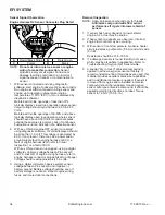
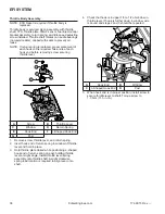
Fuel injector mounts on throttle body and high pressure
fuel line attaches to cap on fuel injector. Replaceable
O-rings on both ends of injector prevent external fuel
leakage and also insulate it from heat and vibration.
A special clip connects injector and fuel injector cap.
O-rings and retaining clip must be replaced any time fuel
injector is separated from its normal mounting position.
When key switch is on, fuel pump will pressurize high
pressure fuel line to 50 psi, and voltage is present at
injector. At proper instant, ECU completes ground circuit,
energizing injector. Valve needle in injector is opened
electromagnetically, and pressure in high pressure fuel
line forces fuel down through injector. Director plate at tip
of injector contains a series of calibrated openings which
directs fuel into intake passage in a cone-shaped spray
pattern.
Injector has sequential fueling that opens and closes
once every other crankshaft revolution. Amount of fuel
injected is controlled by ECU and determined by length
of time valve needle is held open, also referred to as
injection duration or pulse width. Time injector is open
(milliseconds) may vary in duration depending on speed
and load requirements of engine.
A high-voltage, solid-state, battery ignition system is
used with EFI system. ECU controls ignition output and
timing through transistorized control of primary current
delivered to coil. Based on input from crankshaft position
sensor, ECU determines correct fi ring point for speed at
which engine is running. At proper instant, it interrupts
fl ow of primary current in coil, causing electromagnetic
fl ux fi eld to collapse. Flux collapse induces an
instantaneous high voltage in coil secondary which is
strong enough to bridge gap on spark plug. Coil fi res
every other revolution.
Equipment this engine powers has a starter generator,
refer to equipment manufacturer's manual for charging
system troubleshooting information.
An electric in-tank fuel pump (OEM supplied) is used to
transfer fuel in EFI system. Fuel pump is regulated at
350 kilopascals (50 psi).
When key switch is turned ON and all safety switch
requirements are met, ECU activates fuel pump for up to
six seconds (prime process), which pressurizes system
for start-up. If key switch is not promptly turned to start
position, engine fails to start, or engine is stopped with
key switch ON (as in case of an accident), ECU switches
off pump preventing continued delivery of fuel. Once
engine is running, fuel pump remains on.
A special EFI 10-micron fi lter (OEM supplied) is in fuel
tank. Be sure to use an approved 10-micron fi lter for
replacement. Refer to equipment manufacturer's manual
for information.
High pressure fuel line assembly (OEM supplied)
attaches to injector cap and fuel pump using connectors.
High pressure fuel line feeds fuel to top of injector
through injector cap.
Vent hose assembly (OEM supplied) is intended to vent
fuel vapor out of fuel tank, through an OEM supplied
carbon canister and then directs all fuel vapor into purge
port located on throttle body.
Summary of Contents for Carryall 300 2021
Page 2: ......
Page 16: ......
Page 551: ...80 2018 by Kohler Co All rights reserved KohlerEngines com 17 690 15 Rev...
Page 565: ...GASOLINE ENGINE HARNESS Wiring Diagrams Gasoline Engine Harness 26...
Page 566: ...Page intentionally left blank...
Page 567: ...GASOLINE KEY START MAIN HARNESS Wiring Diagrams Gasoline Key Start Main Harness 26...
Page 568: ...Page intentionally left blank...
Page 569: ...GASOLINE PEDAL START MAIN HARNESS Wiring Diagrams Gasoline Pedal Start Main Harness 26...
Page 570: ...Page intentionally left blank...
Page 571: ...GASOLINE INSTRUMENT PANEL HARNESS Wiring Diagrams Gasoline Instrument Panel Harness 26...
Page 572: ...Page intentionally left blank...
Page 573: ...GASOLINE FNR HARNESS Wiring Diagrams Gasoline FNR Harness 26...
Page 574: ...Page intentionally left blank...
Page 575: ...ELECTRIC MAIN HARNESS Wiring Diagrams Electric Main Harness 26...
Page 576: ...Page intentionally left blank...
Page 577: ...ELECTRIC INSTRUMENT PANEL HARNESS Wiring Diagrams Electric Instrument Panel Harness 26...
Page 578: ...Page intentionally left blank...
Page 579: ...ELECTRIC ACCESSORIES HARNESS Wiring Diagrams Electric Accessories Harness 26...
Page 580: ...Page intentionally left blank...
Page 588: ...NOTES...
Page 589: ...NOTES...
Page 590: ...NOTES...
Page 591: ...NOTES...
Page 592: ...NOTES...
Page 593: ...NOTES...
Page 594: ...NOTES...
Page 595: ......
Page 596: ......


