


16
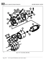
Motor Disassembly
ELECTRIC VEHICLE - MOTOR
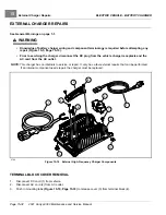
MOTOR DISASSEMBLY
1.
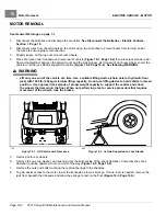
Before beginning disassembly, place match marks on the motor end cap and motor frame.
2.
Remove speed sensor and magnet.
2.1.
Remove the two screws (25) and clamp that secure the speed sensor (10) to the end cap (11)
.
2.2.
Remove the screw securing the magnet to the armature shaft
.
2.3.
Inspect the speed sensor magnet.
See Speed Sensor Magnet Inspection on page 16-11.
3.
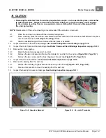
Loosen, but do not remove, the two screws securing the end cap to the motor frame
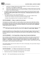
750
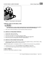
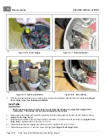
Figure 16-6
End Cap Disengagement
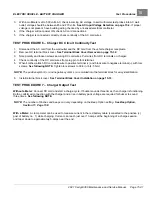
751
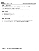
Figure 16-7
End Cap Removal
4.
Orient the motor so that the splined end of the armature is facing down.
5.
Inspect the area where the end cap mates with the motor frame. If the end cap appears to be loose where it
connects to the motor frame, go to step 6; otherwise, disengage the end cap from the motor frame using the
following procedure:
5.1.
With the end cap bolts loose (about 1/4 inch (6.3 mm) between the end cap and the head of the bolt), place
a socket on the head of the bolt.
See following CAUTION.
CAUTION
• Ensure that there is sufficient thread engagement of the end cap bolts before proceeding. Performing
the procedure without having adequate thread engagement could damage the motor frame, end
cap, or end cap bolts.
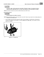
5.2.
Gently tap each bolt, alternating between blows, until the end cap and motor frame become disengaged
6.
Remove the two end cap bolts.
7.
Remove the end cap and armature from the motor frame
.
8.
Inspect the brush springs for proper tension.
See Motor Brush, Spring, and Terminal Insulator Inspection on
9.
Remove the armature from the end cap bearing.
See following CAUTION and NOTE.
Page 16-6
2021 Carryall 300 Maintenance and Service Manual
Summary of Contents for Carryall 300 2021
Page 2: ......
Page 16: ......
Page 551: ...80 2018 by Kohler Co All rights reserved KohlerEngines com 17 690 15 Rev...
Page 565: ...GASOLINE ENGINE HARNESS Wiring Diagrams Gasoline Engine Harness 26...
Page 566: ...Page intentionally left blank...
Page 567: ...GASOLINE KEY START MAIN HARNESS Wiring Diagrams Gasoline Key Start Main Harness 26...
Page 568: ...Page intentionally left blank...
Page 569: ...GASOLINE PEDAL START MAIN HARNESS Wiring Diagrams Gasoline Pedal Start Main Harness 26...
Page 570: ...Page intentionally left blank...
Page 571: ...GASOLINE INSTRUMENT PANEL HARNESS Wiring Diagrams Gasoline Instrument Panel Harness 26...
Page 572: ...Page intentionally left blank...
Page 573: ...GASOLINE FNR HARNESS Wiring Diagrams Gasoline FNR Harness 26...
Page 574: ...Page intentionally left blank...
Page 575: ...ELECTRIC MAIN HARNESS Wiring Diagrams Electric Main Harness 26...
Page 576: ...Page intentionally left blank...
Page 577: ...ELECTRIC INSTRUMENT PANEL HARNESS Wiring Diagrams Electric Instrument Panel Harness 26...
Page 578: ...Page intentionally left blank...
Page 579: ...ELECTRIC ACCESSORIES HARNESS Wiring Diagrams Electric Accessories Harness 26...
Page 580: ...Page intentionally left blank...
Page 588: ...NOTES...
Page 589: ...NOTES...
Page 590: ...NOTES...
Page 591: ...NOTES...
Page 592: ...NOTES...
Page 593: ...NOTES...
Page 594: ...NOTES...
Page 595: ......
Page 596: ......


