11
Fault Descriptions
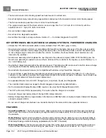
CONTROLLER DIAGNOSTIC TOOL (CDT)
What it means:
This is a symptom, not a cause. The controller records the number of times this occurs.
What to do:
Charge batteries. If fault occurs more frequently than normal, test battery pack. Section 14 — Electric
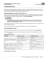
MAIN WELDED
If the speed controller detects that the solenoid contacts are welded closed, a
main welded
fault is detected.
What it means:
The solenoid contact is welded closed and will not dropout when pedal is released, or key switch
is turned to OFF, or FNR is switched to N.
What to do:
Replace solenoid. If vehicle continues to operate at half speed, check accessory wiring.
HIGH SPEED WALKAWAY
If the controller receives a signal to activate walk away braking while the vehicle is moving at a speed greater than 2
mph (3.2 km/h), the controller registers a
high speed walkaway fault
.
What it means:
This is a symptom, not a cause. The key switch was turned to OFF while the vehicle was coasting
faster than 2 mph (3.2 km/h).
What to do:
Most likely, this is due to driver error. If not, check speed sensor on motor and key switch for proper
operation.
SPEED SENSOR
If the speed controller does not detect pulses from the speed sensor while the controller outputs power (greater than
75% armature PWM) to the motor, a
speed sensor
fault is detected.
What it means:
Speed sensor is not working. Check connection.
What to do:
Replace speed sensor.
MAIN DRIVER ON
If the field-effect transistor (FET) that controls the closing of the solenoid contacts is found to be energized when it
should not be, a
main driver on
fault is detected by the speed controller.
What it means:
The controller FET controlling the energizing of the solenoid is on (or energized) when it should not
be. This causes main contactors to stay engaged. Pin 12 provides ground for the solenoid coil when FORWARD,
REVERSE, KEY, or FOOT INPUT is present at the controller. If the ground continues to be present once either KEY,
FOOT, FORWARD or REVERSE INPUT is removed,
main driver on
is detected.
What to do:
Replace controller.
MAIN COIL OPEN
If the speed controller determines that the solenoid is not closing as a result of a solenoid coil failure, a
main coil
open fault
is detected.
What it means:
An open circuit in the solenoid coil. It could be in either the ground side or B+ side of the circuit.
What to do:
Check for a broken or disconnected blue wire on the B+ side of the solenoid coil, a broken or disconnected
blue/white wire on the B- side of the solenoid coil, a broken coil wire inside the solenoid which would result in zero
ohms resistance reading, a defective coil which could result in very low coil resistance (usually less than 40 ohms;
Page 11-20
2021 Carryall 300 Maintenance and Service Manual
Summary of Contents for Carryall 300 2021
Page 2: ......
Page 16: ......
Page 551: ...80 2018 by Kohler Co All rights reserved KohlerEngines com 17 690 15 Rev...
Page 565: ...GASOLINE ENGINE HARNESS Wiring Diagrams Gasoline Engine Harness 26...
Page 566: ...Page intentionally left blank...
Page 567: ...GASOLINE KEY START MAIN HARNESS Wiring Diagrams Gasoline Key Start Main Harness 26...
Page 568: ...Page intentionally left blank...
Page 569: ...GASOLINE PEDAL START MAIN HARNESS Wiring Diagrams Gasoline Pedal Start Main Harness 26...
Page 570: ...Page intentionally left blank...
Page 571: ...GASOLINE INSTRUMENT PANEL HARNESS Wiring Diagrams Gasoline Instrument Panel Harness 26...
Page 572: ...Page intentionally left blank...
Page 573: ...GASOLINE FNR HARNESS Wiring Diagrams Gasoline FNR Harness 26...
Page 574: ...Page intentionally left blank...
Page 575: ...ELECTRIC MAIN HARNESS Wiring Diagrams Electric Main Harness 26...
Page 576: ...Page intentionally left blank...
Page 577: ...ELECTRIC INSTRUMENT PANEL HARNESS Wiring Diagrams Electric Instrument Panel Harness 26...
Page 578: ...Page intentionally left blank...
Page 579: ...ELECTRIC ACCESSORIES HARNESS Wiring Diagrams Electric Accessories Harness 26...
Page 580: ...Page intentionally left blank...
Page 588: ...NOTES...
Page 589: ...NOTES...
Page 590: ...NOTES...
Page 591: ...NOTES...
Page 592: ...NOTES...
Page 593: ...NOTES...
Page 594: ...NOTES...
Page 595: ......
Page 596: ......

