ELECTRIC VEHICLE - BATTERY CHARGER
Charger Troubleshooting
15
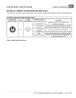
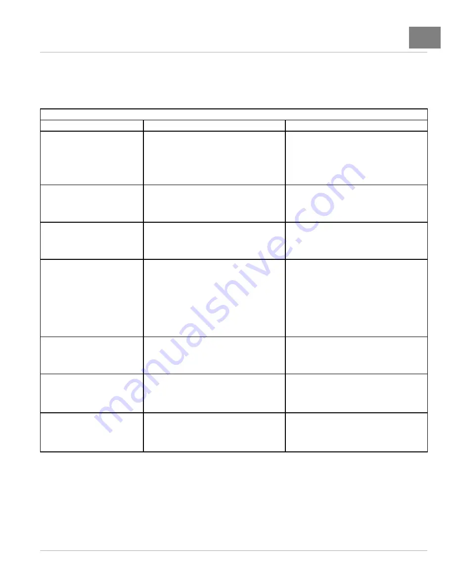
ONBOARD CHARGER FAULT CODES
The “E” and “F” codes will appear in the display panel followed by three numbers and a period to indicate the different
conditions.
_
ONBOARD CHARGER FAULT CODES
FAULT CODE
DESCRIPTION
SOLUTIONS
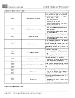
F-0-0-1
F-0-0-2
F-0-0-3
F-0-0-4
F-0-0-5
F-0-0-6
Internal charger fault
• Remove the AC power supply and the battery for
a minimum of 30 seconds.
E-0-0-1
E-0-2-1
Battery high voltage
• Check the battery voltage and cable connections.
• Check the battery size and condition.
• This error will automatically clear once the condi-
tion has been corrected.
E-0-0-2
E-0-2-2
Battery low voltage
• Check the battery voltage and cable connections.
• Check the battery size and condition.
• This error will automatically clear once the condi-
tion has been corrected.
E-0-0-3
Charge timeout caused by battery pack not reaching
required voltage within safe time limit
Possible causes:
Charger output reduced due to
high temperatures, poor battery health, discharged
battery, and/or the battery is not connected correctly.
• Operate at lower ambient temperature.
• Replace the battery pack.
• Check the DC connections.
• This error will automatically clear once the
charger is reset by cycling DC.
E-0-0-4
Battery could not meet minimum voltage
• Check for shorted or damaged cells.
• Replace the battery pack.
• This error will automatically clear once the
charger is reset by cycling DC.
E-0-0-5
Charger temperature limit exceeded
• Ensure sufficient cooling air flow and reset the
charger by disconnecting the AC cord for 10 min-
utes. Reconnect the AC cord.
• This error will automatically clear once the condi-
tion has been corrected.
E-0-0-6
Low AC voltage error
• Connect the charger to an AC source that pro-
vides stable AC between 85 - 270 VAC / 45 - 65
Hz.
• This error will automatically clear once the condi-
tion has been corrected.
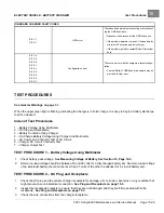
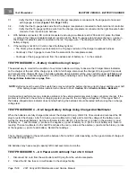
TABLE CONTINUED ON NEXT PAGE
2021 Carryall 300 Maintenance and Service Manual
Page 15-27
Summary of Contents for Carryall 300 2021
Page 2: ......
Page 16: ......
Page 551: ...80 2018 by Kohler Co All rights reserved KohlerEngines com 17 690 15 Rev...
Page 565: ...GASOLINE ENGINE HARNESS Wiring Diagrams Gasoline Engine Harness 26...
Page 566: ...Page intentionally left blank...
Page 567: ...GASOLINE KEY START MAIN HARNESS Wiring Diagrams Gasoline Key Start Main Harness 26...
Page 568: ...Page intentionally left blank...
Page 569: ...GASOLINE PEDAL START MAIN HARNESS Wiring Diagrams Gasoline Pedal Start Main Harness 26...
Page 570: ...Page intentionally left blank...
Page 571: ...GASOLINE INSTRUMENT PANEL HARNESS Wiring Diagrams Gasoline Instrument Panel Harness 26...
Page 572: ...Page intentionally left blank...
Page 573: ...GASOLINE FNR HARNESS Wiring Diagrams Gasoline FNR Harness 26...
Page 574: ...Page intentionally left blank...
Page 575: ...ELECTRIC MAIN HARNESS Wiring Diagrams Electric Main Harness 26...
Page 576: ...Page intentionally left blank...
Page 577: ...ELECTRIC INSTRUMENT PANEL HARNESS Wiring Diagrams Electric Instrument Panel Harness 26...
Page 578: ...Page intentionally left blank...
Page 579: ...ELECTRIC ACCESSORIES HARNESS Wiring Diagrams Electric Accessories Harness 26...
Page 580: ...Page intentionally left blank...
Page 588: ...NOTES...
Page 589: ...NOTES...
Page 590: ...NOTES...
Page 591: ...NOTES...
Page 592: ...NOTES...
Page 593: ...NOTES...
Page 594: ...NOTES...
Page 595: ......
Page 596: ......

