EFI SYSTEM
36
17 690 15 Rev. --
KohlerEngines.com
Injector clogging is usually caused by a buildup of
deposits on director plate, restricting fl ow of fuel,
resulting in a poor spray pattern. Some contributing
factors to injector clogging include higher than normal
operating temperatures, short operating intervals, and
dirty, incorrect, or poor quality fuel.
Cleaning of clogged injector is not recommended; it
should be replaced. Additives and higher grades of fuel
can be used as a preventative measure if clogging has
been a problem.
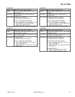
An electrical problem usually will cause injector to stop
functioning. Several methods may be used to check if
injector is operating.
1. With engine running at idle, listen for a buzzing or
clicking sound.
2. Disconnect electrical connector from injector and
engine should stop running. If engine continues to
run, disconnect vent line at air cleaner base. If
engine continues to run, injector is suspect.
If an injector is not operating, it can indicate either a bad
injector, or a wiring/electrical connection problem. Check
as follows:
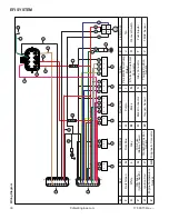
1. Disconnect electrical connector from injector. Plug a
12 volt noid light into connector.
2. Make sure all safety switch requirements are met.
Crank engine and check for fl ashing of noid light.
a. If fl ashing occurs, use an ohmmeter (Rx1 scale)
and check resistance of injector across two
terminals. Proper resistance is 11-13 Ω. If injector
resistance is correct, check whether connector
and injector terminals are making a good
connection. If resistance is not correct, replace
injector.
Check all electrical connections, connectors, and wiring
harness leads if resistance is incorrect.
Injector leakage is very unlikely, but in those rare
instances it can be internal (past tip of valve needle),
or external (weeping around injector O-ring). Loss
of system pressure from leakage can cause hot
restart problems and longer cranking times. Refer to
Disassembly for removal of injector.
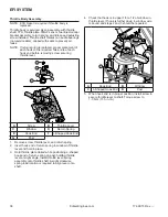
1. Remove throttle body from engine leaving TPS, high
pressure fuel line, injector and fuel line connections
intact. Discard old gaskets.
2. Position throttle body over an appropriate container
to capture fuel and turn key switch ON to activate
fuel pump and pressurize system. Do not turn switch
to START position.
3. If injector exhibits leakage of more than two to four
drops per minute from tip, or shows any sign of
leakage around outer shell, turn ignition switch OFF
and replace injector as follows.
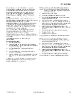
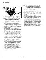
4. Depressurize fuel system and disconnect high
pressure fuel line from fuel injector cap.
5. Clean any dirt accumulation from sealing/mounting
area of faulty injector and disconnect electrical
connector.
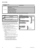
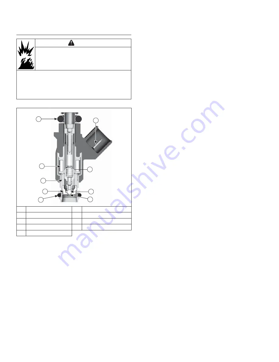
Fuel Injector
WARNING
Explosive Fuel can cause fi res and severe
burns.
Do not fi ll fuel tank while engine is hot or
running.
Gasoline is extremely fl ammable and its vapors can
explode if ignited. Store gasoline only in approved
containers, in well ventilated, unoccupied buildings,
away from sparks or fl ames. Spilled fuel could ignite if it
comes in contact with hot parts or sparks from ignition.
Never use gasoline as a cleaning agent.
Details
A
B
C
E
F
H
I
G
D
A
Electrical Connection
B
Upper O-ring
C
Solenoid Winding
D
Armature
E
Valve Housing
F
Valve Seat
G
Valve End
H
Lower O-ring
I
Director Plate
NOTE: Do not apply voltage to fuel injector. Excessive
voltage will burn out injector. Do not ground
injector with ignition ON. Injector will open/turn
on if relay is energized.
NOTE: When cranking engine with injector
disconnected, fault codes will be registered in
ECU and will need to be cleared using software
fault clear or an ECU Reset and TPS Learn
Procedure.
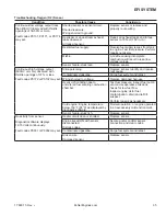
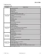
Injector problems typically fall into three general
categories: electrical, dirty/clogged, or leakage. Injector
problems due to dirt or clogging are generally unlikely
due to design of injector, high fuel pressure, and
detergent additives in gasoline. Symptoms that could
be caused by dirty/clogged injector include rough idle,
hesitation/stumbling during acceleration, or triggering of
fault codes related to fuel delivery.
Summary of Contents for Carryall 300 2021
Page 2: ......
Page 16: ......
Page 551: ...80 2018 by Kohler Co All rights reserved KohlerEngines com 17 690 15 Rev...
Page 565: ...GASOLINE ENGINE HARNESS Wiring Diagrams Gasoline Engine Harness 26...
Page 566: ...Page intentionally left blank...
Page 567: ...GASOLINE KEY START MAIN HARNESS Wiring Diagrams Gasoline Key Start Main Harness 26...
Page 568: ...Page intentionally left blank...
Page 569: ...GASOLINE PEDAL START MAIN HARNESS Wiring Diagrams Gasoline Pedal Start Main Harness 26...
Page 570: ...Page intentionally left blank...
Page 571: ...GASOLINE INSTRUMENT PANEL HARNESS Wiring Diagrams Gasoline Instrument Panel Harness 26...
Page 572: ...Page intentionally left blank...
Page 573: ...GASOLINE FNR HARNESS Wiring Diagrams Gasoline FNR Harness 26...
Page 574: ...Page intentionally left blank...
Page 575: ...ELECTRIC MAIN HARNESS Wiring Diagrams Electric Main Harness 26...
Page 576: ...Page intentionally left blank...
Page 577: ...ELECTRIC INSTRUMENT PANEL HARNESS Wiring Diagrams Electric Instrument Panel Harness 26...
Page 578: ...Page intentionally left blank...
Page 579: ...ELECTRIC ACCESSORIES HARNESS Wiring Diagrams Electric Accessories Harness 26...
Page 580: ...Page intentionally left blank...
Page 588: ...NOTES...
Page 589: ...NOTES...
Page 590: ...NOTES...
Page 591: ...NOTES...
Page 592: ...NOTES...
Page 593: ...NOTES...
Page 594: ...NOTES...
Page 595: ......
Page 596: ......

