12
Troubleshooting
ELECTRIC VEHICLE - ELECTRICAL SYSTEM
TROUBLESHOOTING
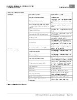
TROUBLESHOOTING GUIDE 2
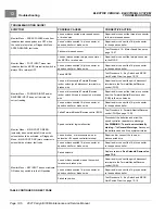
SYMPTOM
POSSIBLE CAUSES
CORRECTIVE ACTION
Speed sensor disconnected or failed
Test Procedure 12 – Motor Speed Sensor on
Incorrect speed setting
To change the programmed top speed of
the vehicle, an OEM-level CDT handheld
programmer must be used
Wiring – improperly wired
Check vehicle wiring.
and 10k Ohm Resistor Locations on page
Batteries – batteries discharged
Charge batteries
MCOR malfunction
Test Procedure 11 – MCOR Voltage on page
Motor – loose wires
Inspect and tighten all wire connections at the
motor.
Failed motor
Replace motor.
Vehicle is over-loaded
Ensure that vehicle is not over-loaded before
returning to operation.
Speed controller failure
Replace speed controller.
Controller Removal on page 13-7.
Brakes – improperly adjusted
Section 6 — Wheel Brake Assemblies
Vehicle runs slowly
Tires – under-inflated or flat tires
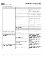
Vehicle operates but has points in pedal
travel where it does not maintain speed nor
accelerate
MCOR malfunction
Test Procedure 11 – MCOR Voltage on page
Vehicle reaches top speed before 100% pedal
travel is reached
Speed controller – failed throttle resistor(s)
Replace speed controller.
Controller Removal on page 13-7.
Wiring – improperly wired
Check vehicle wiring.
and 10k Ohm Resistor Locations on page
Vehicle operates, but motor braking function
does not
Speed sensor disconnected or failed
Test Procedure 12 – Motor Speed Sensor on
Forward/Neutral/Reverse control (FNR) –
improperly wired
Test Procedure 6 – Forward/Neutral/Reverse
Motor – improperly wired
Check motor wiring.
and 10k Ohm Resistor Locations on page
Vehicle will run in forward, but not in reverse or
will run in reverse but not forward
Speed controller – improperly wired or failed
speed controller FET
Check vehicle wiring.
and 10k Ohm Resistor Locations on page
TABLE CONTINUED ON NEXT PAGE
Page 12-10
2021 Carryall 300 Maintenance and Service Manual
Summary of Contents for Carryall 300 2021
Page 2: ......
Page 16: ......
Page 551: ...80 2018 by Kohler Co All rights reserved KohlerEngines com 17 690 15 Rev...
Page 565: ...GASOLINE ENGINE HARNESS Wiring Diagrams Gasoline Engine Harness 26...
Page 566: ...Page intentionally left blank...
Page 567: ...GASOLINE KEY START MAIN HARNESS Wiring Diagrams Gasoline Key Start Main Harness 26...
Page 568: ...Page intentionally left blank...
Page 569: ...GASOLINE PEDAL START MAIN HARNESS Wiring Diagrams Gasoline Pedal Start Main Harness 26...
Page 570: ...Page intentionally left blank...
Page 571: ...GASOLINE INSTRUMENT PANEL HARNESS Wiring Diagrams Gasoline Instrument Panel Harness 26...
Page 572: ...Page intentionally left blank...
Page 573: ...GASOLINE FNR HARNESS Wiring Diagrams Gasoline FNR Harness 26...
Page 574: ...Page intentionally left blank...
Page 575: ...ELECTRIC MAIN HARNESS Wiring Diagrams Electric Main Harness 26...
Page 576: ...Page intentionally left blank...
Page 577: ...ELECTRIC INSTRUMENT PANEL HARNESS Wiring Diagrams Electric Instrument Panel Harness 26...
Page 578: ...Page intentionally left blank...
Page 579: ...ELECTRIC ACCESSORIES HARNESS Wiring Diagrams Electric Accessories Harness 26...
Page 580: ...Page intentionally left blank...
Page 588: ...NOTES...
Page 589: ...NOTES...
Page 590: ...NOTES...
Page 591: ...NOTES...
Page 592: ...NOTES...
Page 593: ...NOTES...
Page 594: ...NOTES...
Page 595: ......
Page 596: ......


