EFI SYSTEM
34
17 690 15 Rev. --
KohlerEngines.com
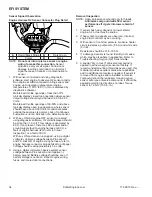
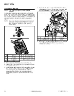
Sensor Signal Observation
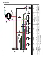
Engine Harness O2 Sensor Connector Plug Detail
D
B C
A
A
Red w/Black Stripe
B
Dark Green
C
Purple
D
Black
NOTE:
Do not cut into or pierce sensor or engine
wiring to make this connection.
Sensor
produces a very small signal. Corrosion or
damage to wiring could lead to an incorrect
signal because of repairs or contamination to
sensor.
1. With sensor connected and using diagnostic
software, start engine to observe O2 sensor activity.
Run engine at suffi cient speed to bring sensor and
engine up to operating temperature (engine
temperature of 150°F (66°C) or more displayed by
diagnostic software).
Maintained throttle openings of less than 37%
typically display closed loop operation where sensor
output voltage should cycle between 0.05 to 0.95
Volts.
Maintained throttle openings of 38-50% and above
typically display open loop operation where sensor
should have above 0.500 Volt. Occasional spikes
outside these values is normal. Lack of continuous
fl uctuation is not an indication of a defective sensor.
2. With key ON and engine OFF, sensor connected,
using diagnostic software, O2 volts displayed should
be more than 1.0 volt. This voltage is generated by
ECU. If not present, there may be a power and/or
ground supply fault to engine harness or ECU, a
fault of engine harness itself (refer to Visual
Inspection), or a fault of ECU.
With key ON and sensor unplugged, using a digital
voltmeter, observe voltage between Pin socket C
and Pin socket D of engine wiring harness (refer to
engine harness connector plug detail at top of page).
Voltage should read approximately 5.0 volts.
3. Using a digital voltmeter, observe system sensor
voltage between Pin socket A and negative (-)
battery ground. Battery voltage should be seen. If
battery voltage is not seen, inspect engine wiring,
fuses, and/or electrical connections.
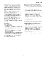
Removal Inspection
NOTE: Apply anti-seize compound only to threads.
Anti-seize compound will aff ect sensor
performance if it gets into lower shield of
sensor.
1. If sensor has heavy deposits on lower shield,
engine, oil, or fuel may be source.
2. If heavy carbon deposits are observed, incorrect
engine fuel control may be occurring.
3. With sensor at room temperature, measure heater
circuit resistance, purple wire (Pin A) and white wire
(Pin B).
Resistance should be 16.5-19.5 Ω.
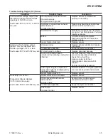
4. If a damaged sensor is found, identify root cause,
which may be elsewhere in application. Refer to
Troubleshooting-Oxygen (O2) Sensor table.
5. A special "dry to touch" anti-seize compound is
applied to all new oxygen sensors at factory. If
recommended mounting thread sizes are used, this
material provides excellent anti-seize capabilities
and no additional anti-seize is needed. If sensor is
removed from engine and reinstalled, anti-seize
compound should be reapplied. Use an oxygen
sensor safe type anti-seize compound. It should be
applied according to directions on label. Torque
sensor to 18 N·m (159 in. lb.).
Summary of Contents for Carryall 300 2021
Page 2: ......
Page 16: ......
Page 551: ...80 2018 by Kohler Co All rights reserved KohlerEngines com 17 690 15 Rev...
Page 565: ...GASOLINE ENGINE HARNESS Wiring Diagrams Gasoline Engine Harness 26...
Page 566: ...Page intentionally left blank...
Page 567: ...GASOLINE KEY START MAIN HARNESS Wiring Diagrams Gasoline Key Start Main Harness 26...
Page 568: ...Page intentionally left blank...
Page 569: ...GASOLINE PEDAL START MAIN HARNESS Wiring Diagrams Gasoline Pedal Start Main Harness 26...
Page 570: ...Page intentionally left blank...
Page 571: ...GASOLINE INSTRUMENT PANEL HARNESS Wiring Diagrams Gasoline Instrument Panel Harness 26...
Page 572: ...Page intentionally left blank...
Page 573: ...GASOLINE FNR HARNESS Wiring Diagrams Gasoline FNR Harness 26...
Page 574: ...Page intentionally left blank...
Page 575: ...ELECTRIC MAIN HARNESS Wiring Diagrams Electric Main Harness 26...
Page 576: ...Page intentionally left blank...
Page 577: ...ELECTRIC INSTRUMENT PANEL HARNESS Wiring Diagrams Electric Instrument Panel Harness 26...
Page 578: ...Page intentionally left blank...
Page 579: ...ELECTRIC ACCESSORIES HARNESS Wiring Diagrams Electric Accessories Harness 26...
Page 580: ...Page intentionally left blank...
Page 588: ...NOTES...
Page 589: ...NOTES...
Page 590: ...NOTES...
Page 591: ...NOTES...
Page 592: ...NOTES...
Page 593: ...NOTES...
Page 594: ...NOTES...
Page 595: ......
Page 596: ......


