13
Charge Indicator Light
ELECTRIC VEHICLE - ELECTRICAL
COMPONENTS
2.
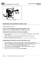
Install the three screws (1) that secure the receptacle to the grille. Tighten screws to 16 in·lb (1.8 N·m).
3.
Connect three-pin connector.
4.
Install cowl.
See Cowl Installation on page 4-4.
5.
Place the Run/Tow switch in the TOW position and connect the batteries.
See Connect the Batteries – Electric
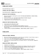
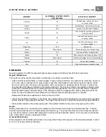
CHARGE INDICATOR LIGHT
See General Warnings on page 1-1.
TESTING THE CHARGE INDICATOR LIGHT
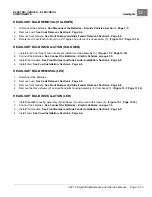
CHARGE INDICATOR LIGHT REMOVAL
1.
Disconnect the batteries and discharge the controller.
See Disconnect the Batteries – Electric Vehicles,
2.
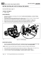
Remove instrument panel.
See Instrument Panel Removal on page 4-9.
3.
Disconnect the wires at the warning light.
4.
Press the two retaining tabs and remove the light from the instrument panel.
CHARGE INDICATOR LIGHT INSTALLATION
1.
Install light into instrument panel.
2.
Connect wires to the warning light.
3.
Install the instrument panel.
See Instrument Panel Installation on page 4-9.
4.
Connect the batteries.
See Connect the Batteries – Electric Vehicles, Section 1, Page 1-5.
DC/DC CONVERTER
DC/DC CONVERTER REMOVAL
The DC/DC Converter is mounted to the chassis under the passenger-side floorboard.
1.
Disconnect the batteries and discharge the controller.
See Disconnect the Batteries – Electric Vehicles
2.
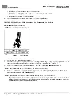
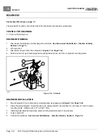
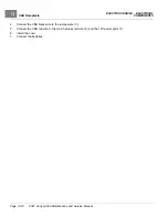
Disconnect the DC/DC converter three pin (1) and two pin (2) plugs from the wire harness (3).
3.
Remove the two locknuts (4) securing the DC/DC converter (5) to the frame and remove converter.
Page 13-10
2021 Carryall 300 Maintenance and Service Manual
Summary of Contents for Carryall 300 2021
Page 2: ......
Page 16: ......
Page 551: ...80 2018 by Kohler Co All rights reserved KohlerEngines com 17 690 15 Rev...
Page 565: ...GASOLINE ENGINE HARNESS Wiring Diagrams Gasoline Engine Harness 26...
Page 566: ...Page intentionally left blank...
Page 567: ...GASOLINE KEY START MAIN HARNESS Wiring Diagrams Gasoline Key Start Main Harness 26...
Page 568: ...Page intentionally left blank...
Page 569: ...GASOLINE PEDAL START MAIN HARNESS Wiring Diagrams Gasoline Pedal Start Main Harness 26...
Page 570: ...Page intentionally left blank...
Page 571: ...GASOLINE INSTRUMENT PANEL HARNESS Wiring Diagrams Gasoline Instrument Panel Harness 26...
Page 572: ...Page intentionally left blank...
Page 573: ...GASOLINE FNR HARNESS Wiring Diagrams Gasoline FNR Harness 26...
Page 574: ...Page intentionally left blank...
Page 575: ...ELECTRIC MAIN HARNESS Wiring Diagrams Electric Main Harness 26...
Page 576: ...Page intentionally left blank...
Page 577: ...ELECTRIC INSTRUMENT PANEL HARNESS Wiring Diagrams Electric Instrument Panel Harness 26...
Page 578: ...Page intentionally left blank...
Page 579: ...ELECTRIC ACCESSORIES HARNESS Wiring Diagrams Electric Accessories Harness 26...
Page 580: ...Page intentionally left blank...
Page 588: ...NOTES...
Page 589: ...NOTES...
Page 590: ...NOTES...
Page 591: ...NOTES...
Page 592: ...NOTES...
Page 593: ...NOTES...
Page 594: ...NOTES...
Page 595: ......
Page 596: ......

