11
Parameters
CONTROLLER DIAGNOSTIC TOOL (CDT)
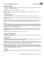
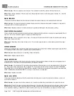
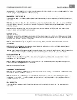
The Parameters menu is where you can view and modify the settings of the controller's adjustable parameters.
Navigate through this complex menu using the arrow keys, +/- keys, and softkeys.
The parameters displayed will
depend on the access level of the handset.
Be aware when changing parameter settings, the new values replace the earlier values. If you make adjustments that
you don’t like, and wish you could return to the earlier values, you cannot do this unless you have written down those
earlier settings (which is unlikely) or unless you have saved them. To save your parameter settings, use the “Save .cpf
File” function in the Programming menu; see Plot & Log on page 11-25. Your parameter settings will then be saved in a
.cpf file. You can save as many .cpf files as you desire, and you can create unique names for them. If you prefer,
each .cpf can automatically be given a name consisting of the date and time when it was created; see the “Text for
save as” item in the HHP (Handheld Programmer) Settings menu; see Plot & Log on page 11-25. For information
on creating names, see
Using the Keyboard
in the CDT Owner's Manual.
SETTINGS
Speed Setting
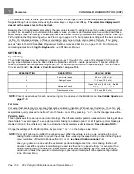
The vehicle’s top speed can be changed by selecting values 1 through 3. If a value of 4 is displayed for the speed
setting, a special access code has been entered to place the vehicle in “private speed mode.” A speed setting of 4
cannot be selected with the
speed setting
menu item. For additional information on speed setting 4, refer to
See Code A, Code B, and Code C on page 11-8.
_
SPEED SETTING
DESCRIPTION
VEHICLE SPEED
1
Commercial speed
8.0 mph (12.9 km/h)
2
Slow golf speed
11.4 mph (18.3 km/h)
3
Normal golf speed
Typical 14.8 mph (23.8 km/h).
4
Private speed mode
19.2 mph (30.9 km/h)
NOTE:
Present speed values for each speed setting may be observed in the Monitor menu.
Fast Accel
Fast accel
(fast acceleration) is an option that can be enabled or disabled. With
fast accel
turned on, the vehicle will
accelerate at a noticeably faster rate. With this feature turned off, the vehicle speed will gradually increase, even if the
accelerator is quickly pressed to the floor. Turn the feature on or off by pressing “+” or “–” on the change value button.
Pedal Up Mode
Three options exist for
pedal up mode
(motor braking). When the accelerator pedal is released, motor braking will slow
the vehicle to “near zero speed” when pedal up motor braking is enabled (option 1 or 2). If pedal up motor braking is
disabled (option 0), the vehicle will coast to a stop when the accelerator pedal is released.
See following NOTE.
Change the settings of the Pedal Up Mode by pressing “+” or “–” on the change value button.
NOTE:
Pedal Up Mode does not affect top vehicle speed. When the vehicle is going down an incline, the motor
braking function will activate to prevent the vehicle from exceeding the speed setting defined in the Program
menu, regardless of Pedal Up Mode setting (0,1, or 2).
See Speed Setting on page 11-6.
When going down an incline with the accelerator pedal partially pressed, the motor braking function will
activate to assist the operator in maintaining a speed less than the top speed setting. For example, if the
vehicle is going down an incline with the accelerator pedal pressed half way, the motor braking function
will activate to assist the operator in maintaining a speed approximately half of the speed setting defined
in the Program Menu.
Page 11-6
2021 Carryall 300 Maintenance and Service Manual
Summary of Contents for Carryall 300 2021
Page 2: ......
Page 16: ......
Page 551: ...80 2018 by Kohler Co All rights reserved KohlerEngines com 17 690 15 Rev...
Page 565: ...GASOLINE ENGINE HARNESS Wiring Diagrams Gasoline Engine Harness 26...
Page 566: ...Page intentionally left blank...
Page 567: ...GASOLINE KEY START MAIN HARNESS Wiring Diagrams Gasoline Key Start Main Harness 26...
Page 568: ...Page intentionally left blank...
Page 569: ...GASOLINE PEDAL START MAIN HARNESS Wiring Diagrams Gasoline Pedal Start Main Harness 26...
Page 570: ...Page intentionally left blank...
Page 571: ...GASOLINE INSTRUMENT PANEL HARNESS Wiring Diagrams Gasoline Instrument Panel Harness 26...
Page 572: ...Page intentionally left blank...
Page 573: ...GASOLINE FNR HARNESS Wiring Diagrams Gasoline FNR Harness 26...
Page 574: ...Page intentionally left blank...
Page 575: ...ELECTRIC MAIN HARNESS Wiring Diagrams Electric Main Harness 26...
Page 576: ...Page intentionally left blank...
Page 577: ...ELECTRIC INSTRUMENT PANEL HARNESS Wiring Diagrams Electric Instrument Panel Harness 26...
Page 578: ...Page intentionally left blank...
Page 579: ...ELECTRIC ACCESSORIES HARNESS Wiring Diagrams Electric Accessories Harness 26...
Page 580: ...Page intentionally left blank...
Page 588: ...NOTES...
Page 589: ...NOTES...
Page 590: ...NOTES...
Page 591: ...NOTES...
Page 592: ...NOTES...
Page 593: ...NOTES...
Page 594: ...NOTES...
Page 595: ......
Page 596: ......

