


CONTROLLER DIAGNOSTIC TOOL (CDT)
Parameters
11
_
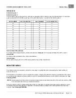
PEDAL UP MODE SETTING
MODE
OPERATION DESCRIPTION
0
Off
Pedal up motor braking is disabled
1
Mild pedal up
Mild pedal up motor braking
2
Aggressive pedal up
Aggressive pedal up motor braking
Speed Cal
The
speed cal
(speed calibration) menu item allows the user to fine tune the vehicle speed. This feature cannot be used
to increase the vehicle speed. The range for speed calibration is 0 to 30. Each time the number is increased, the top
speed will be decreased by 0.1 mph (0.16 km/h). The top vehicle speed will be determined by the
speed setting
menu
item and the speed calibration setting. For example, if the speed setting is set for a value of 2 (11.4 mph (18.3 km/h)),
and the speed calibration is set for 5, the total top speed of the vehicle should be approximately 10.9 mph (17.5 km/h).
NOTE:
The SPEED CAL function will not be necessary in most golf applications since the speed setting 3 is finely
adjustable with S3 FWD SPEED.
See S3 FWD Speed on page 11-7.
S3 FWD Speed
The
s3 fwd speed
option allows for adjustability of the SPEED 3 speed setting. From the factory,
s3 fwd speed
will be
set to one of 4 options: 12.4, 13.2, 14.0 and 14.8 mph (20.0, 21.3, 22.6 and 23.8 km/h, respectively). The default
s3
fwd speed
is 14.8 mph (23.8 km/h). The
s3 fwd speed
may be adjusted with the handset from 11.4 to 14.8 mph (18.3 to
23.8 km/h) in 0.1 mph (0.16 km/h) increments. The speed value chosen for
s3 fwd speed
may also be observed in the
monitor menu.
See Vehicle Speeds on page 11-13.
To fine tune vehicle top speed in normal golf speed range (12.4 to 14.8 mph (20.0 to 23.8 km/h)):
1.
Access the
program
menu, then the
speed setting
menu with the navigation keys.
2.
Select Speed Setting 3 with the change value buttons.
3.
Access the
program
menu and the
s3 fwd speed
menu with the navigation keys.
4.
Use the change value buttons to select desired speed.
Control Mode
The
control mode
option is used to configure the 1515 controller for different modes of speed control operation.
Four modes are avaiable:
• 0 = Standard: Uses maximum speeds defined by the
S1
through
S4 Fwd Speed
,
Rev Speed
, and
Speed Cal
parameters.
• 1 = LIN (Local Interconnect bus) (i.e. Guardian or Visage): Uses maximum speeds assigned to a particular location
or area as defined by the fleet operator; however, these defined speeds can not override maximums set in the
S1
through
S4 Fwd Speed
,
Rev Speed
, and
Speed Cal
parameters.
• 2 = ES-Protocol (UpLink): Uses maximum speeds assigned to a particular location or area as defined by the fleet
operator; however, these defined speeds can not override previously set values from other
control mode
options. To
avoid this, after changing the
control mode
to 2, cycle power to the controller by placing the Run/Tow Switch in the
TOW position for 30 seconds. Then return it to RUN.
• 3 = Deterrent Demo Mode: Uses maximum speeds defined by the
deterrent demo
setting to demonstrate the
automatic speed control features of Guardian and UpLink.
See Deterrent Demo on page 11-8.
Anti-Tamper
The
anti-tamper
setting defines maximum speed if the Anti-Tamper fault is triggered (e.g. controller is disconnected
from the Guardian or Visage system). These speeds can only be activated if the Control Mode option is set to 1
(Guardian/Visage) and are intended to be a deterrent. Factory default setting is 1.
• 0 = OFF; uses controller configured speed (
S1
through
S4 Fwd Speed
,
Rev Speed
, and
Speed Cal
parameters)
even if the Anti-Tamper fault is triggered
2021 Carryall 300 Maintenance and Service Manual
Page 11-7
Summary of Contents for Carryall 300 2021
Page 2: ......
Page 16: ......
Page 551: ...80 2018 by Kohler Co All rights reserved KohlerEngines com 17 690 15 Rev...
Page 565: ...GASOLINE ENGINE HARNESS Wiring Diagrams Gasoline Engine Harness 26...
Page 566: ...Page intentionally left blank...
Page 567: ...GASOLINE KEY START MAIN HARNESS Wiring Diagrams Gasoline Key Start Main Harness 26...
Page 568: ...Page intentionally left blank...
Page 569: ...GASOLINE PEDAL START MAIN HARNESS Wiring Diagrams Gasoline Pedal Start Main Harness 26...
Page 570: ...Page intentionally left blank...
Page 571: ...GASOLINE INSTRUMENT PANEL HARNESS Wiring Diagrams Gasoline Instrument Panel Harness 26...
Page 572: ...Page intentionally left blank...
Page 573: ...GASOLINE FNR HARNESS Wiring Diagrams Gasoline FNR Harness 26...
Page 574: ...Page intentionally left blank...
Page 575: ...ELECTRIC MAIN HARNESS Wiring Diagrams Electric Main Harness 26...
Page 576: ...Page intentionally left blank...
Page 577: ...ELECTRIC INSTRUMENT PANEL HARNESS Wiring Diagrams Electric Instrument Panel Harness 26...
Page 578: ...Page intentionally left blank...
Page 579: ...ELECTRIC ACCESSORIES HARNESS Wiring Diagrams Electric Accessories Harness 26...
Page 580: ...Page intentionally left blank...
Page 588: ...NOTES...
Page 589: ...NOTES...
Page 590: ...NOTES...
Page 591: ...NOTES...
Page 592: ...NOTES...
Page 593: ...NOTES...
Page 594: ...NOTES...
Page 595: ......
Page 596: ......