16
Motor Removal
ELECTRIC VEHICLE - MOTOR
MOTOR REMOVAL
See General Warnings on page 1-1.
1.
Disconnect the batteries and discharge the controller.
See Disconnect the Batteries – Electric Vehicles,
2.
Disconnect wires from the terminals on the motor using two wrenches to prevent posts from turning. Label
the wires to ensure proper reconnection.
3.
Slightly loosen all the lug nuts on both rear wheels.
4.
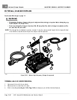
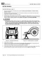
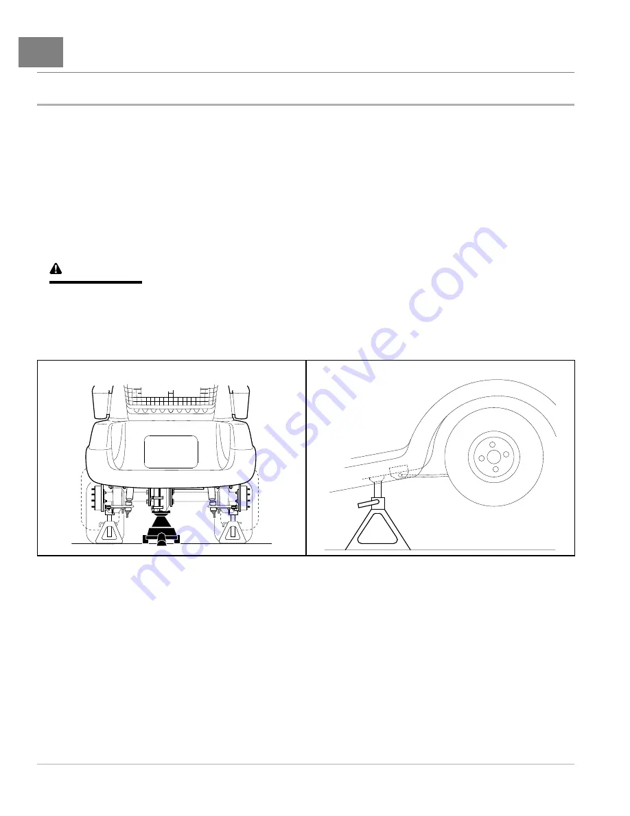
Place floor jack under transaxle and raise rear of vehicle
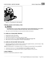
then place jack stands under
frame crossmember between the spring mount and the side stringer, just forward of each rear wheel. Lower the
vehicle to let the jack stands support the vehicle
See following WARNING.
WARNING
• Lift only one end of the vehicle at a time. Use a suitable lifting device (chain hoist or hydraulic floor
jack) with 1000 lb. (454 kg) minimum lifting capacity. Do not use lifting device to hold vehicle in raised
position. Use approved jack stands of proper weight capacity to support the vehicle and chock
the wheels that remain on the floor. When not performing a test or service procedure that requires
movement of the wheels, lock the brakes.
729
Figure 16-1
Lift Vehicle with Floor Jack
682
Figure 16-2
Vehicle Supported on Jack Stands
5.
Remove both rear wheels.
6.
Remove the nut, cup washer, and bushing from the bottom side of the shock absorber. Compress the shock
absorber (pushing upwards) to move it out of the way
.
7.
Remove the nuts and bolts mounting the rear leaf springs to the shackles.
8.
To gain easier access to the motor, lower the transaxle as low as it will go. If more room is needed, remove the
jack from beneath the transaxle and allow the springs to rest on the floor
.
Page 16-4
2021 Carryall 300 Maintenance and Service Manual
Summary of Contents for Carryall 300 2021
Page 2: ......
Page 16: ......
Page 551: ...80 2018 by Kohler Co All rights reserved KohlerEngines com 17 690 15 Rev...
Page 565: ...GASOLINE ENGINE HARNESS Wiring Diagrams Gasoline Engine Harness 26...
Page 566: ...Page intentionally left blank...
Page 567: ...GASOLINE KEY START MAIN HARNESS Wiring Diagrams Gasoline Key Start Main Harness 26...
Page 568: ...Page intentionally left blank...
Page 569: ...GASOLINE PEDAL START MAIN HARNESS Wiring Diagrams Gasoline Pedal Start Main Harness 26...
Page 570: ...Page intentionally left blank...
Page 571: ...GASOLINE INSTRUMENT PANEL HARNESS Wiring Diagrams Gasoline Instrument Panel Harness 26...
Page 572: ...Page intentionally left blank...
Page 573: ...GASOLINE FNR HARNESS Wiring Diagrams Gasoline FNR Harness 26...
Page 574: ...Page intentionally left blank...
Page 575: ...ELECTRIC MAIN HARNESS Wiring Diagrams Electric Main Harness 26...
Page 576: ...Page intentionally left blank...
Page 577: ...ELECTRIC INSTRUMENT PANEL HARNESS Wiring Diagrams Electric Instrument Panel Harness 26...
Page 578: ...Page intentionally left blank...
Page 579: ...ELECTRIC ACCESSORIES HARNESS Wiring Diagrams Electric Accessories Harness 26...
Page 580: ...Page intentionally left blank...
Page 588: ...NOTES...
Page 589: ...NOTES...
Page 590: ...NOTES...
Page 591: ...NOTES...
Page 592: ...NOTES...
Page 593: ...NOTES...
Page 594: ...NOTES...
Page 595: ......
Page 596: ......

