


31
17 690 15 Rev. --
KohlerEngines.com
EFI SYSTEM
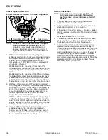
Crankshaft Position Sensor
A sealed, non-serviceable assembly. If fault code P0337
is present and engine does not start/run, proceed to step
1. If P0337 is present and engine operates, clear codes
and retest. If Fault Code diagnosis indicates a problem
within this area, test and correct as follows.
1. Inspect wiring and connections for damage or
problems.
2. Make sure engine has resistor type spark plug.
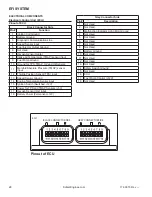
3. Disconnect Black connector from ECU.
4. Connect an ohmmeter between #4 and #13 pin
terminals. A resistance value of 325-395 Ω at room
temperature (20°C, 68°F) should be obtained. If
resistance is correct, remove blower housing to
check sensor mounting, fl ywheel teeth (damage,
run-out, etc.), and fl ywheel key. Follow procedures in
Disassembly to remove blower housing.
5. Disconnect crankshaft position sensor connector
from wiring harness. Test resistance between
terminals. A reading of 325-395 Ω should again be
obtained.
a. If resistance is incorrect, remove screw securing
sensor to bracket and replace sensor.
b. If resistance in step 4 was incorrect, but
resistance of sensor alone was correct, test wire
harness circuits between sensor connector
terminals and corresponding pin terminals (#4
and #13) in main connector. Correct any
observed problem, reconnect sensor, and
perform step 4 again.
6. When fault is corrected and engine starts, clear fault
codes following ECU Reset procedure.
Throttle Position Sensor (TPS)
TPS is a sealed, non-serviceable assembly. If diagnosis
indicates a bad sensor, complete replacement is
necessary. If a fault code indicates a problem with TPS,
it can be tested as follows:
Diagnostics of sensor: ECU will have electrical faults
captured in fault codes P0122 and P0123. Fault code
P0122 detecting low voltage, open circuit, and P0123 for
high voltage conditions between ECU, wire harness, and
sensor. Tip: when working with any electrical connection,
remember to keep connections clean & dry. This is best
accomplished by cleaning connection thoroughly prior
to disassembly. Contaminated sensor connections can
cause premature engine faults. Functionally testing
sensor cannot be done with simple resistance checks.
If either of these two faults is present or a TPS fault is
suspected, recommended diagnostic test is as follows:
If a computer with diagnostic software is available
Observe throttle percent and raw TPS values through
diagnostic software. With diagnostic software
communicating to ECU and key ON engine not running,
these values can be observed while throttle is moved
from closed to full open position. There should be a
smooth and repeatable throttle percent value starting
at closed position reading between 0 and 3% to WOT
position reading of 93 to 100%. If one of these values
is outside of specifi ed range and output transitions in a
smooth manner, reset ECU and run test again.
Since there is no longer any wear elements inside
sensor, most likely faults will be in electrical connections
between sensor and wire harness and wire harness to
ECU. With service software communicating to ECU and
engine not running, a small load or gentle back and forth
motion can be applied to connectors or wires just outside
connectors to detect a faulty connection.
I
f only a volt meter is available
Measure voltage supply to sensor from ECU. This
voltage should be 5.00 +/- 0.20 volts. This can be
measured by gently probing terminals B & C on harness
side with TPS connector removed from TPS and key
ON. This will generate a P0122 fault that can be cleared
with an ECU reset. If voltage is low, battery, harness and
ECU should be investigated. If supply voltage is good,
plug sensor back into harness. Probe sensor signal
wire with volt meter, terminal A at TPS or pin Black 12 at
ECU. This signal should start between 0.6-1.2 volts at
low idle and grow smoothly as throttle is opened to 4.3-
4.8 volts at full open (WOT). Since there is no longer any
wear elements inside sensor, most likely faults will be in
electrical connections between sensor and wire harness
and wire harness to ECU.
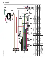
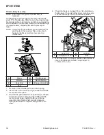
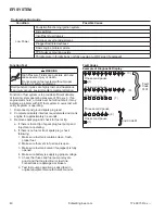
Replace TPS
C
D
C
A
B
A
A
TPS Screws
B
TPS
C
Magnet Assembly
D
Magnet Installation
Depth
Magnet assembly is captured in a small plastic housing
that is press fi t to end of throttle shaft. If replacement is
required, it can be replaced as follows:
1. Remove screws securing TPS to throttle body.
Remove sensor from throttle body, exposing round
magnet assembly.
2. A pair of fl at blade screw drivers or a spanner tool
can be used to pry this off shaft. Caution should be
used to avoid damage to machined fl at surface that
sensor seals against. Also, make sure throttle blade
is in full open position to avoid driving throttle blade
into throttle bore causing damage to blade and/or
bore.
3. When replacing magnet assembly, alignment is
critical. There is a D-shaped drive feature on end of
shaft and a matching pocket in magnet assembly.
On outer diameter of magnet assembly is a notch
that aligns with center of fl at feature of D. Align this
notch and fl at of D feature in shaft and preassemble
parts.
Summary of Contents for Carryall 300 2021
Page 2: ......
Page 16: ......
Page 551: ...80 2018 by Kohler Co All rights reserved KohlerEngines com 17 690 15 Rev...
Page 565: ...GASOLINE ENGINE HARNESS Wiring Diagrams Gasoline Engine Harness 26...
Page 566: ...Page intentionally left blank...
Page 567: ...GASOLINE KEY START MAIN HARNESS Wiring Diagrams Gasoline Key Start Main Harness 26...
Page 568: ...Page intentionally left blank...
Page 569: ...GASOLINE PEDAL START MAIN HARNESS Wiring Diagrams Gasoline Pedal Start Main Harness 26...
Page 570: ...Page intentionally left blank...
Page 571: ...GASOLINE INSTRUMENT PANEL HARNESS Wiring Diagrams Gasoline Instrument Panel Harness 26...
Page 572: ...Page intentionally left blank...
Page 573: ...GASOLINE FNR HARNESS Wiring Diagrams Gasoline FNR Harness 26...
Page 574: ...Page intentionally left blank...
Page 575: ...ELECTRIC MAIN HARNESS Wiring Diagrams Electric Main Harness 26...
Page 576: ...Page intentionally left blank...
Page 577: ...ELECTRIC INSTRUMENT PANEL HARNESS Wiring Diagrams Electric Instrument Panel Harness 26...
Page 578: ...Page intentionally left blank...
Page 579: ...ELECTRIC ACCESSORIES HARNESS Wiring Diagrams Electric Accessories Harness 26...
Page 580: ...Page intentionally left blank...
Page 588: ...NOTES...
Page 589: ...NOTES...
Page 590: ...NOTES...
Page 591: ...NOTES...
Page 592: ...NOTES...
Page 593: ...NOTES...
Page 594: ...NOTES...
Page 595: ......
Page 596: ......


