


ELECTRIC VEHICLE - ELECTRICAL SYSTEM
TROUBLESHOOTING
Test Procedures
12
If the meter does not indicate continuity, check and repair related connections, Run/Tow switch and wiring. If
necessary, replace affected wire harness, charger receptacle or Run/Tow switch.
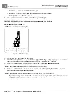
7.
When finished, install 15-amp fuse and fuse cover.
TEST PROCEDURE 11 – MCOR Voltage
See General Warnings on page 1-1.
NOTE:
This is a voltage test.
The accelerator position, which is proportional to the MCOR voltage, can be displayed with the CDT handset. If a CDT
handset is not available, go to
MCOR Voltage Test without the CDT Handset
.
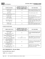
The following are potential MCOR symptoms:
• Vehicle will not drive due to no FOOT INPUT to the controller.
• Vehicle will not reach top speed because MCOR does not reach 100% throttle position.
• Vehicle does not maintain speed nor will it accelerate due to MCOR having a “dead-spot” in its pedal travel.
• The voltage signal from the MCOR randomly or sporadically fluctuates with pedal at rest, during pedal travel and
with pedal fully pressed.
MCOR Voltage Test with the CDT Handset
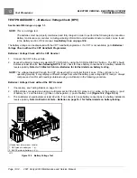
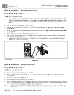
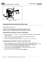
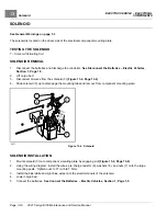
1.
Place chocks at the front wheels and lift the rear of the vehicle with a chain hoist or floor jack. Position jack
stands under the frame rails just forward of each spring mount.
See WARNING “Lift only one end...” in
. See also following WARNING.
WARNING
• The key switch should be placed in the OFF position and left in the OFF position for the duration
of this test.
2.
Connect the CDT to the vehicle.
3.
Access the Monitor menu and select THROTTLE % by using the SCROLL DISPLAY buttons.
4.
The CDT should indicate 0% with the pedal not pressed. While monitoring the CDT display screen, slowly press
the accelerator pedal. As the pedal is pressed, the CDT should indicate a steady, incremental rise from 0% (pedal
not pressed) to 100% (pedal fully pressed).
See following NOTE.
NOTE:
Observe closely to see if throttle input percentage randomly or sporadically fluctuates with pedal at rest, during
pedal travel and with pedal fully pressed. If it fluctuates, the MCOR is defective and must be replaced.
5.
If the MCOR passes the previous test, press and hold the accelerator pedal to the floor. By hand, gently move
the pedal from side to side and see if the throttle input percentage fluctuates from 100%. If it fluctuates, the
MCOR is defective and must be replaced.
6.
If throttle input percentage does not reach 100% in the previous steps, go to
MCOR Voltage Test without
the CDT Handset.
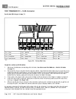
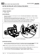
MCOR Voltage Test without the CDT Handset
1.
Place chocks at the front wheels and lift the rear of the vehicle with a chain hoist or floor jack. Position jack
stands under the frame rails just forward of each spring mount.
See WARNING “Lift only one end...” in
. See also following WARNING.
2021 Carryall 300 Maintenance and Service Manual
Page 12-25
Summary of Contents for Carryall 300 2021
Page 2: ......
Page 16: ......
Page 551: ...80 2018 by Kohler Co All rights reserved KohlerEngines com 17 690 15 Rev...
Page 565: ...GASOLINE ENGINE HARNESS Wiring Diagrams Gasoline Engine Harness 26...
Page 566: ...Page intentionally left blank...
Page 567: ...GASOLINE KEY START MAIN HARNESS Wiring Diagrams Gasoline Key Start Main Harness 26...
Page 568: ...Page intentionally left blank...
Page 569: ...GASOLINE PEDAL START MAIN HARNESS Wiring Diagrams Gasoline Pedal Start Main Harness 26...
Page 570: ...Page intentionally left blank...
Page 571: ...GASOLINE INSTRUMENT PANEL HARNESS Wiring Diagrams Gasoline Instrument Panel Harness 26...
Page 572: ...Page intentionally left blank...
Page 573: ...GASOLINE FNR HARNESS Wiring Diagrams Gasoline FNR Harness 26...
Page 574: ...Page intentionally left blank...
Page 575: ...ELECTRIC MAIN HARNESS Wiring Diagrams Electric Main Harness 26...
Page 576: ...Page intentionally left blank...
Page 577: ...ELECTRIC INSTRUMENT PANEL HARNESS Wiring Diagrams Electric Instrument Panel Harness 26...
Page 578: ...Page intentionally left blank...
Page 579: ...ELECTRIC ACCESSORIES HARNESS Wiring Diagrams Electric Accessories Harness 26...
Page 580: ...Page intentionally left blank...
Page 588: ...NOTES...
Page 589: ...NOTES...
Page 590: ...NOTES...
Page 591: ...NOTES...
Page 592: ...NOTES...
Page 593: ...NOTES...
Page 594: ...NOTES...
Page 595: ......
Page 596: ......


