


17
Transaxle Disassembly, Inspection, and Assembly
ELECTRIC VEHICLE - TRANSAXLE
NOTE:
Damaged or worn gears should be replaced as sets.
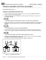
TRANSAXLE ASSEMBLY
CAUTION
• Do not press against the bearing outer race.
• The housing and all parts must be wiped clean and dry before reassembly.
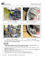
1.
If bearings (13) were removed during disassembly, install new bearings using an arbor press
.
2.
Assemble the differential gear case.
2.1.
Install the pin (31)
. Apply a small amount of oil to all thrust plates and to both
ends of the pin.
2.2.
Install the hex bolts (33) and output gear (32). Tighten bolts to 58 ft·lb (78.6 N·m).
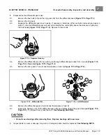
3.
Press a new bearing (18) onto the intermediate gear assembly
4.
Press new bearing (16) onto input pinion gear (17).
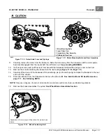
5.
Apply grease to the lip of the new oil seal (10) and install the seal using a transaxle pinion seal tool. The lip of the
oil seal should face the inside of the transaxle housing. Make sure the seal is firmly seated.
6.
Install the differential assembly, the intermediate gear assembly, and the input pinion gear simultaneously. Be
sure all bearings are seated properly in the housing. Rotate the input shaft to check for smooth gear operation
.
7.
Install both dowel pins (25) in the transaxle housing (20)
.
8.
Install left half of transaxle housing:
8.1.
Place a 1/8-inch (3 mm) bead of Three Bond liquid gasket on mating surface of housing.
8.2.
Install left half of transaxle housing (20)
8.3.
Install eleven bolts (24) in the case housing and tighten to 19 ft·lb (25.7 N·m). Type G transaxles have no
shims or gasket.
8.4.
Install axle tube (14 and 35) with bolts (8)
. Tighten the bolts to 37 ft·lb (50.2 N·m).
9.
Install the brake assemblies as instructed.
See Wheel Brake Assemblies Section.
10.
Apply a small amount of grease to the lip of the oil seal (15)
.
See following CAUTION.
CAUTION
• Clean any residual oil from the exposed end of the axle shaft and from the oil seal area prior to
installing the axle shaft to prevent oil from coming in contact with brakes.
11.
Install the rear axle onto the transaxle.
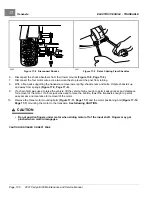
11.1.
Insert the splined end of the axle shaft into the axle tube. Be careful not to damage the seal on the inside of
the axle tube hub. Advance the shaft through to the bearing on the shaft, and rotate it to align the shaft
splines with the splined bore of the differential gear. Continue advancing the shaft until the bearing on the
axle is firmly seated within the axle tube hub seat.
11.2.
Using 90° internal snap ring pliers (0.090 tip), attach the internal retaining ring into the axle tube hub so that
it seats against the axle bearing assembly and into the machined slot in the inside wall of the axle tube
hub
.
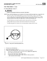
11.3.
Place a 1/4 to 3/8-inch (6 to 10 mm) diameter rod against the retaining ring and tap lightly at four or five
locations to ensure it is properly seated.
See following WARNING
.
Page 17-10
2021 Carryall 300 Maintenance and Service Manual
Summary of Contents for Carryall 300 2021
Page 2: ......
Page 16: ......
Page 551: ...80 2018 by Kohler Co All rights reserved KohlerEngines com 17 690 15 Rev...
Page 565: ...GASOLINE ENGINE HARNESS Wiring Diagrams Gasoline Engine Harness 26...
Page 566: ...Page intentionally left blank...
Page 567: ...GASOLINE KEY START MAIN HARNESS Wiring Diagrams Gasoline Key Start Main Harness 26...
Page 568: ...Page intentionally left blank...
Page 569: ...GASOLINE PEDAL START MAIN HARNESS Wiring Diagrams Gasoline Pedal Start Main Harness 26...
Page 570: ...Page intentionally left blank...
Page 571: ...GASOLINE INSTRUMENT PANEL HARNESS Wiring Diagrams Gasoline Instrument Panel Harness 26...
Page 572: ...Page intentionally left blank...
Page 573: ...GASOLINE FNR HARNESS Wiring Diagrams Gasoline FNR Harness 26...
Page 574: ...Page intentionally left blank...
Page 575: ...ELECTRIC MAIN HARNESS Wiring Diagrams Electric Main Harness 26...
Page 576: ...Page intentionally left blank...
Page 577: ...ELECTRIC INSTRUMENT PANEL HARNESS Wiring Diagrams Electric Instrument Panel Harness 26...
Page 578: ...Page intentionally left blank...
Page 579: ...ELECTRIC ACCESSORIES HARNESS Wiring Diagrams Electric Accessories Harness 26...
Page 580: ...Page intentionally left blank...
Page 588: ...NOTES...
Page 589: ...NOTES...
Page 590: ...NOTES...
Page 591: ...NOTES...
Page 592: ...NOTES...
Page 593: ...NOTES...
Page 594: ...NOTES...
Page 595: ......
Page 596: ......


