


19
Starter/Generator
GASOLINE VEHICLE - ELECTRICAL
COMPONENTS
2.
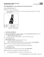
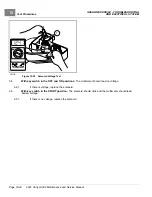
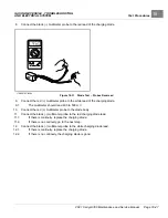
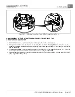
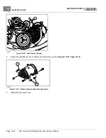
Install the four brushes (27) into their holders and insert the four brush springs (28)
Using a spring scale, test brush spring tension. If any spring has a tension less than 24 ozf (0.68 kgf), replace all
four springs
See following CAUTION.
CAUTION
• When checking brush spring tension, do not push springs beyond the point they would normally be if
there were new brushes installed. Exerting excessive force or pushing brush springs beyond their
normal maximum extension point will damage springs.
0
5
10
15
20
25
30
35
40
45
50
490
Figure 19-6
Brush Spring Tension Test
STARTER/GENERATOR ASSEMBLY
1.
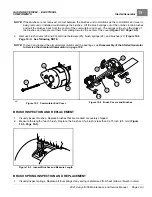
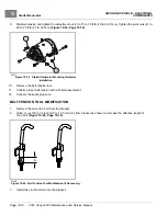
Install the brushes (27) into the holders. Install the terminal hardware (25)
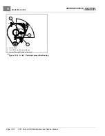
2.
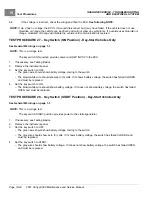
To prevent contact between the brushes and commutator as the commutator is installed, and possible damage
to the brushes, lift the brush springs and pull the brushes back from the center of the commutator end cover.
The springs will rest on the sides of the brushes and help prevent them from sliding towards the center of the
cover
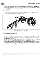
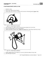
3.
Install the commutator end cover (23) onto the armature shaft. Align the locating pin with the pin hole in the cover.
Install two M6 x 180 mm bolts (20) and tighten to 100 in·lb (11.3 N·m)
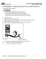
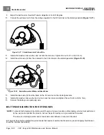
4.
Push the brushes down into the holders. Position springs on the end of the brushes. Install the brush cover (30)
that has the drain hole in it next to the A2 terminal. Install the remaining three brush covers (29) in the openings in
the commutator end cover (23)
.
Page 19-4
2021 Carryall 300 Maintenance and Service Manual
Summary of Contents for Carryall 300 2021
Page 2: ......
Page 16: ......
Page 551: ...80 2018 by Kohler Co All rights reserved KohlerEngines com 17 690 15 Rev...
Page 565: ...GASOLINE ENGINE HARNESS Wiring Diagrams Gasoline Engine Harness 26...
Page 566: ...Page intentionally left blank...
Page 567: ...GASOLINE KEY START MAIN HARNESS Wiring Diagrams Gasoline Key Start Main Harness 26...
Page 568: ...Page intentionally left blank...
Page 569: ...GASOLINE PEDAL START MAIN HARNESS Wiring Diagrams Gasoline Pedal Start Main Harness 26...
Page 570: ...Page intentionally left blank...
Page 571: ...GASOLINE INSTRUMENT PANEL HARNESS Wiring Diagrams Gasoline Instrument Panel Harness 26...
Page 572: ...Page intentionally left blank...
Page 573: ...GASOLINE FNR HARNESS Wiring Diagrams Gasoline FNR Harness 26...
Page 574: ...Page intentionally left blank...
Page 575: ...ELECTRIC MAIN HARNESS Wiring Diagrams Electric Main Harness 26...
Page 576: ...Page intentionally left blank...
Page 577: ...ELECTRIC INSTRUMENT PANEL HARNESS Wiring Diagrams Electric Instrument Panel Harness 26...
Page 578: ...Page intentionally left blank...
Page 579: ...ELECTRIC ACCESSORIES HARNESS Wiring Diagrams Electric Accessories Harness 26...
Page 580: ...Page intentionally left blank...
Page 588: ...NOTES...
Page 589: ...NOTES...
Page 590: ...NOTES...
Page 591: ...NOTES...
Page 592: ...NOTES...
Page 593: ...NOTES...
Page 594: ...NOTES...
Page 595: ......
Page 596: ......


