GASOLINE VEHICLE - TROUBLESHOOTING
AND ELECTRICAL SYSTEM
Test Procedures
18
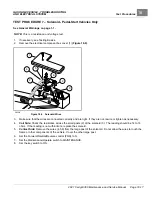
TEST PROCEDURE 16 – Malfunction Indicator Light (MIL)
See General Warnings on page 1-1.
NOTE:
This is a voltage test.
1.
If necessary, see Testing Basics.
2.
Remove the instrument panel.
3.
Make sure that the wires are connected correctly and are tight. If they are not, rewire or tighten as necessary.
4.
Turn the key switch to ON.
5.
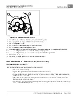
Check for battery voltage at red/green wire to malfunction indicator light (MIL).
5.1.
If there is no voltage, check the key switch.
5.2.
If there is battery voltage, use a test lead to ground the tan wire terminal of the MIL.
5.2.1.
If the light illuminates, the MIL is good.
5.2.2.
If the light does not illuminate, replace the MIL.
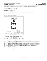
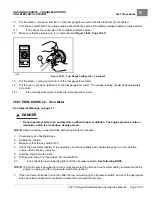
TEST PROCEDURE 17 – Low Oil Warning Light (LED)
See General Warnings on page 1-1.
NOTE:
This is a voltage test.
1.
If necessary, see Testing Basics.
2.
Remove the instrument panel.
3.
Make sure that the wires are connected correctly and are tight. If they are not, rewire or tighten as necessary.
4.
Turn the key switch to ON.
5.
Check for battery voltage at yellow wire to low oil warning light.
5.1.
If there is no voltage, check the key switch.
5.2.
If there is battery voltage, use a test lead to ground the black wire terminal of the low oil warning light.
5.2.1.
If the light illuminates, the low oil warning light is good.
5.2.2.
If the light does not illuminate, replace the low oil warning light.
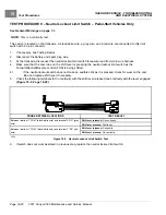
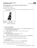
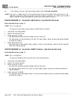
TEST PROCEDURE 18 – Battery Test (Under Load)
See General Warnings on page 1-1.
NOTE:
Keep the battery connected while performing this test procedure.
The voltage reading listed is for electrolyte at 70 °F (21 °C). At lower electrolyte temperatures the voltage
reading will be lower.
1.
If necessary, see Testing Basics.
2.
Set the Forward/Neutral/Reverse control (FNR) to N.
3.
Set the Maintenance/Operate switch to MAINTENANCE.
4.
Put chocks against the wheels.
5.
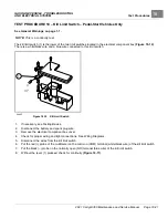
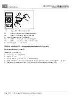
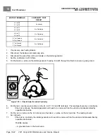
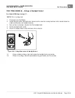
Set a multimeter to 20 VDC.
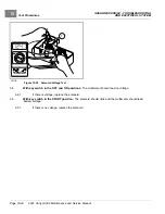
6.
Put the red (+) probe on the F2 (white wire) terminal on the starter/generator
2021 Carryall 300 Maintenance and Service Manual
Page 18-29
Summary of Contents for Carryall 300 2021
Page 2: ......
Page 16: ......
Page 551: ...80 2018 by Kohler Co All rights reserved KohlerEngines com 17 690 15 Rev...
Page 565: ...GASOLINE ENGINE HARNESS Wiring Diagrams Gasoline Engine Harness 26...
Page 566: ...Page intentionally left blank...
Page 567: ...GASOLINE KEY START MAIN HARNESS Wiring Diagrams Gasoline Key Start Main Harness 26...
Page 568: ...Page intentionally left blank...
Page 569: ...GASOLINE PEDAL START MAIN HARNESS Wiring Diagrams Gasoline Pedal Start Main Harness 26...
Page 570: ...Page intentionally left blank...
Page 571: ...GASOLINE INSTRUMENT PANEL HARNESS Wiring Diagrams Gasoline Instrument Panel Harness 26...
Page 572: ...Page intentionally left blank...
Page 573: ...GASOLINE FNR HARNESS Wiring Diagrams Gasoline FNR Harness 26...
Page 574: ...Page intentionally left blank...
Page 575: ...ELECTRIC MAIN HARNESS Wiring Diagrams Electric Main Harness 26...
Page 576: ...Page intentionally left blank...
Page 577: ...ELECTRIC INSTRUMENT PANEL HARNESS Wiring Diagrams Electric Instrument Panel Harness 26...
Page 578: ...Page intentionally left blank...
Page 579: ...ELECTRIC ACCESSORIES HARNESS Wiring Diagrams Electric Accessories Harness 26...
Page 580: ...Page intentionally left blank...
Page 588: ...NOTES...
Page 589: ...NOTES...
Page 590: ...NOTES...
Page 591: ...NOTES...
Page 592: ...NOTES...
Page 593: ...NOTES...
Page 594: ...NOTES...
Page 595: ......
Page 596: ......


