18
Test Procedures
GASOLINE VEHICLE - TROUBLESHOOTING
AND ELECTRICAL SYSTEM
9.2.
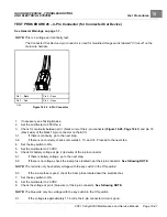
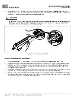
If the voltage is incorrect, check the wiring and then the ECU.
See following NOTE.
NOTE:
If pin 4 has no voltage, the ECU LIN (Local Interconnect bus) may have failed. If the vehicle does not use
Guardian or Visage, the vehicle can be driven and will not show any symptoms. If a vehicle uses Guardian or
Visage, Guardian or Visage will disable the vehicle until communication is restored.
TEST PROCEDURE 27 – Key Switch (ON Position) - Key-Start Vehicles Only
See General Warnings on page 1-1.
NOTE:
This is a voltage test.
The key switch ON position provides power and KEY INPUT to the ECU.
1.
If necessary, see Testing Basics.
2.
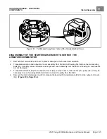
Remove the instrument panel.
3.
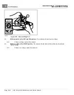
Set the key switch to OFF.
– The green wire should show battery voltage coming to the switch.
– The brown/white wire should show zero (0) volts. If it shows battery voltage, the switch has failed CLOSED
and must be replaced.
4.
Set the key switch to ON.
– The brown/white wire should show battery voltage. If it does not show battery voltage, the switch has failed
OPEN and must be replaced.
TEST PROCEDURE 28 – Key Switch (START Position) - Key-Start Vehicles Only
See General Warnings on page 1-1.
NOTE:
This is a voltage test.
The key switch START position provides power to the starter/generator.
1.
If necessary, see Testing Basics.
2.
Remove the instrument panel.
3.
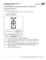
Set the key switch to OFF.
– The green wire should show battery voltage coming to the switch.
– The gray wire should show zero (0) volts. If it shows battery voltage, the switch has failed CLOSED and
must be replaced.
4.
Set the key switch to START.
– The gray wire should show battery voltage. If it does not show battery voltage, the switch has failed OPEN
and must be replaced.
Page 18-42
2021 Carryall 300 Maintenance and Service Manual
Summary of Contents for Carryall 300 2021
Page 2: ......
Page 16: ......
Page 551: ...80 2018 by Kohler Co All rights reserved KohlerEngines com 17 690 15 Rev...
Page 565: ...GASOLINE ENGINE HARNESS Wiring Diagrams Gasoline Engine Harness 26...
Page 566: ...Page intentionally left blank...
Page 567: ...GASOLINE KEY START MAIN HARNESS Wiring Diagrams Gasoline Key Start Main Harness 26...
Page 568: ...Page intentionally left blank...
Page 569: ...GASOLINE PEDAL START MAIN HARNESS Wiring Diagrams Gasoline Pedal Start Main Harness 26...
Page 570: ...Page intentionally left blank...
Page 571: ...GASOLINE INSTRUMENT PANEL HARNESS Wiring Diagrams Gasoline Instrument Panel Harness 26...
Page 572: ...Page intentionally left blank...
Page 573: ...GASOLINE FNR HARNESS Wiring Diagrams Gasoline FNR Harness 26...
Page 574: ...Page intentionally left blank...
Page 575: ...ELECTRIC MAIN HARNESS Wiring Diagrams Electric Main Harness 26...
Page 576: ...Page intentionally left blank...
Page 577: ...ELECTRIC INSTRUMENT PANEL HARNESS Wiring Diagrams Electric Instrument Panel Harness 26...
Page 578: ...Page intentionally left blank...
Page 579: ...ELECTRIC ACCESSORIES HARNESS Wiring Diagrams Electric Accessories Harness 26...
Page 580: ...Page intentionally left blank...
Page 588: ...NOTES...
Page 589: ...NOTES...
Page 590: ...NOTES...
Page 591: ...NOTES...
Page 592: ...NOTES...
Page 593: ...NOTES...
Page 594: ...NOTES...
Page 595: ......
Page 596: ......

